Projects I’m working on appear below. Completed projects get moved off this page and into the Build Diaries list.
updated 25 April 2024
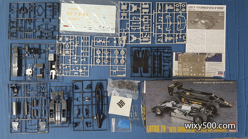
1978 Lotus 79 (Hasegawa, 1:20)
Instead of building another really old F1 kit from the stash, I decided to do this – a new release from Hasegawa, the Lotus 79 from the 1978 German Grand Prix, but this is the Detail Up version that includes extra parts and photo etch. Kit number 52298 (also listed as SP498), it’s 1:20 scale (same as the Tamiya Grand Prix series) in plastic with rubber tyres.
I plan to do this as an out-of-box build of Mario Andretti’s car #5 as he won the race on the way to becoming World Champion.
I did an unboxing video for this kit on YouTube – watch it HERE.
There are LOTS of parts in this kit!
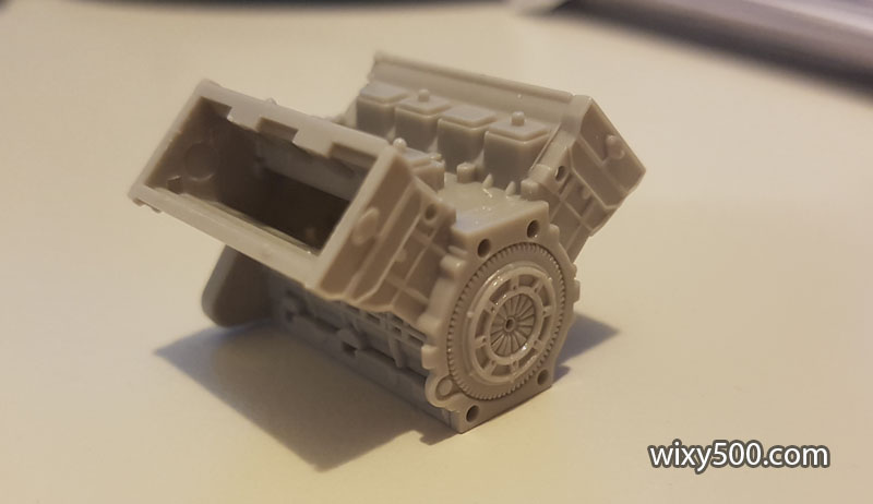
Cosworth DFV engine block goes together quickly. I questioned why Hasegawa bothered to model the flywheel and clutch when it will not be visible once the bellhousing and gearbox go on. But I guess if you were doing a diorama, this could be really handy!
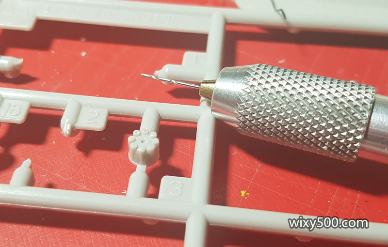
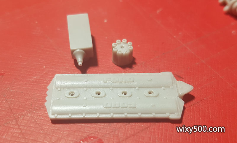
The engine appears quite well detailed, but the kit does not include any ignition leads. I’d like to add some, so need to drill out all the mounting points to glue leads in later in the build. First step is the distributor.
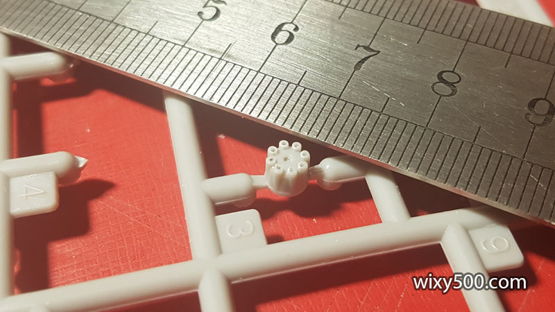
Nine tiny holes drilled. The entire part is only 5mm wide!
Distributor, coil pack and rocker cover (x2) all drilled.
1991 Ferrari 643 (Rosso, 1:8)
I never thought I’d see, never mind build, one of these kits. It’s the big 1/8 scale version of the Ferrari 643 by Japanese manufacturer, Rosso Corporation.
Just after this model was produced in 1992, there was a fire at the Rosso factory which destroyed the production equipment and much of the stock of this model (ref: Wikipedia). The company never recovered and this promising model manufacturer was declared bankrupt.
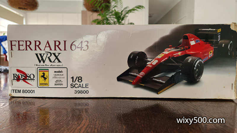
With limited supply reaching retailers, the prices for this kit on eBay are rather spectacular. Cutting edge in its day, the model actually lacks detail that you’d expect in a similar scale modern kit.
I should point out, this kit is not mine. The owner made a start on it many years ago and has commissioned me to finish it off. He’s also given me authority to share the kit and the build process.
We have yet to decide the level of detail for the build. Some beautiful after market items have been produced over the years, but to go “full spec” might cost way more than what the model is worth (assuming the parts can still be found).
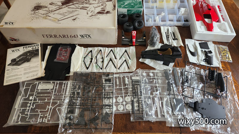
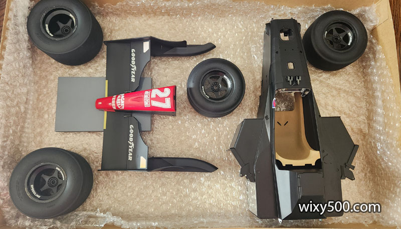
So, this is what we have:
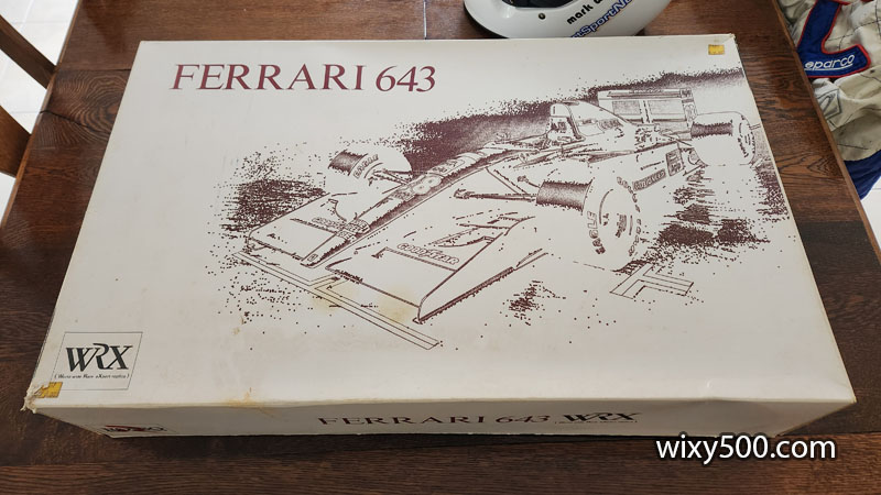
The box is big – 755 x 470 x 150mm. This pic is on the dining table because it won’t fit in my work area!
Rosso Corporation’s first (and last) 1/8 scale Formula One model, item number 80001, officially approved by Ferrari.
All the parts that come in this giant kit. Most of the plastic sprue bags are still sealed, but the owner has opened several to use parts for the section’s he’s already started, such as the nose and base monocoque. The body parts, which are metal, are pre-painted.
Below is a full “What’s in the box” video:
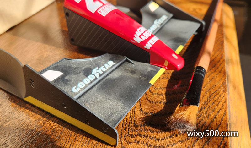
With several parts having been started many years ago, they’ve accumulated quite a bit of dust. I don’t want that getting anywhere else in the build, so clean it up before starting any work.
The nose assembly has been sitting like this in the box for many years, which over time has bent the front wings up quite badly (the central piece is quite heavy as the red bodywork part is metal).
Cleaned parts out of the way in another box until I need them. The nose section is sitting up on a block in the hope some of the wing sag will reverse, but I suspect it will need some heat and persuasion to make it flat once again. No rush yet however, as there’s plenty of other work to get done first.
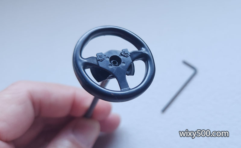
The steering wheel is just black plastic and has already been fitted to the metal steering column with a tiny hex bolt. But I think I can improve the look…
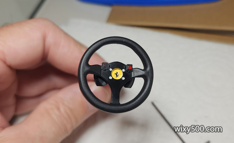
Semi-gloss black was used for the centre piece while the rim was done with black surface primer (to create a bit of a contrasting textured look). Bolt heads and buttons were painted with a small brush. Prancing horse sticker and clear lens cover are kit items.
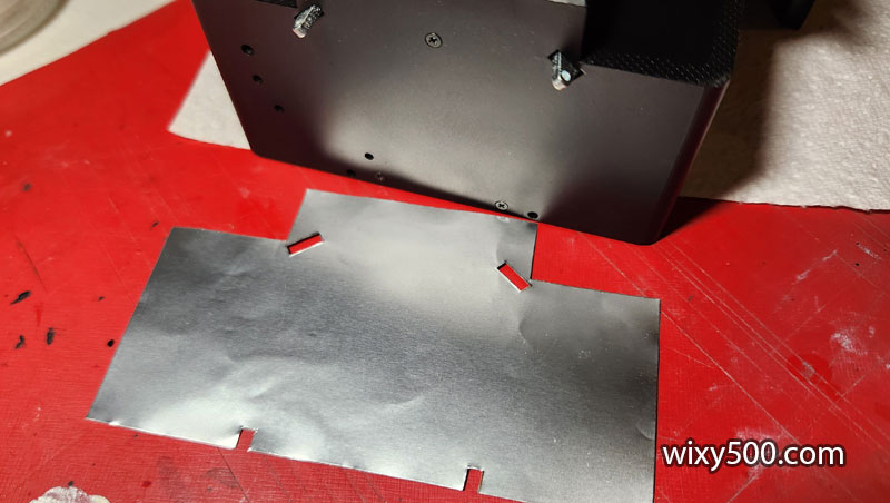
Kit-supplied self-adhesive heat shielding foil has to be cut to allow mounting brackets and screws to pass through.
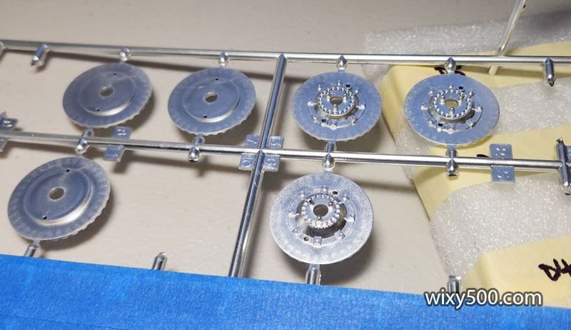
The kit’s brake components are all plated in aluminium/silver colour, which is not correct.
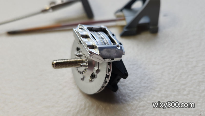
Test fitting the calliper-upright-axle-disc assembly. Even though most of this is hidden once the wheels are fitted, it’s going to look wrong. The kit instructions do not call for any of this to be painted, but I think it needs some colour…
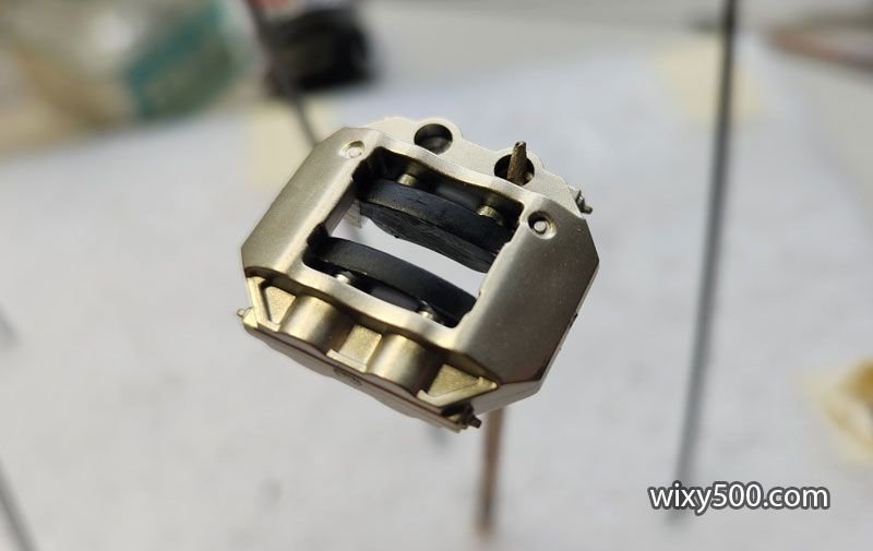
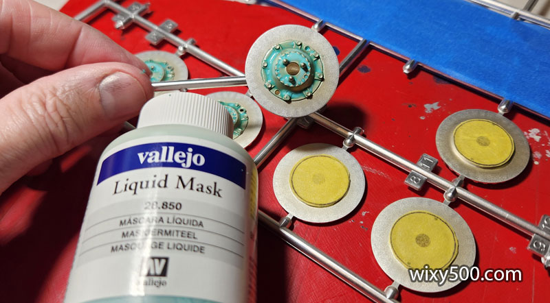
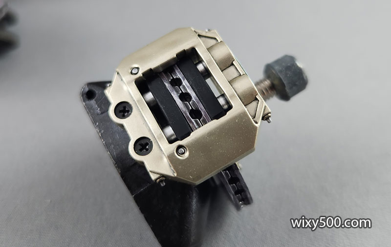
So, pads and pistons are masked off, ready for ‘titanium’ colour (Tamiya TS-87) to represent the anodised finish on the real car.
The pads are hand-painted matt black, but the pistons retain the metallic silver colour.
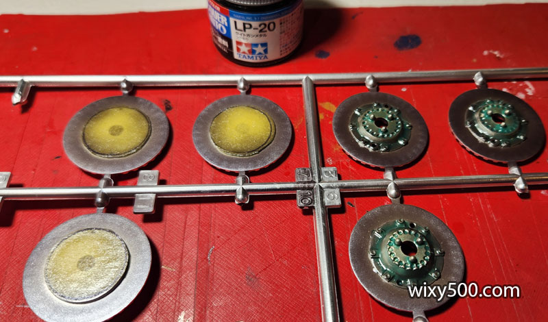
The discs are also sprayed Titanium, then masked off so the rotors can be painted a different colour. Each disc is made of two halves – the back half I used tape cut to shape, while the front halves required Liquid Mask.
Rotor surfaces were then sprayed Tamiya LP-20 Light Gun Metal.
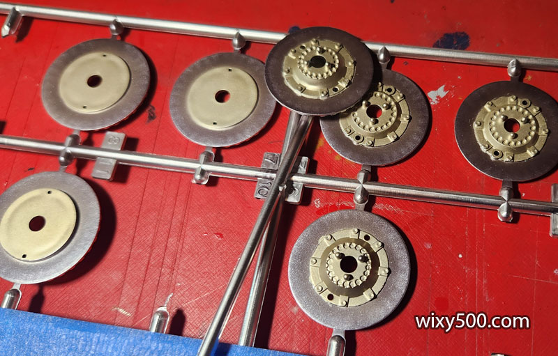
Masks removed.
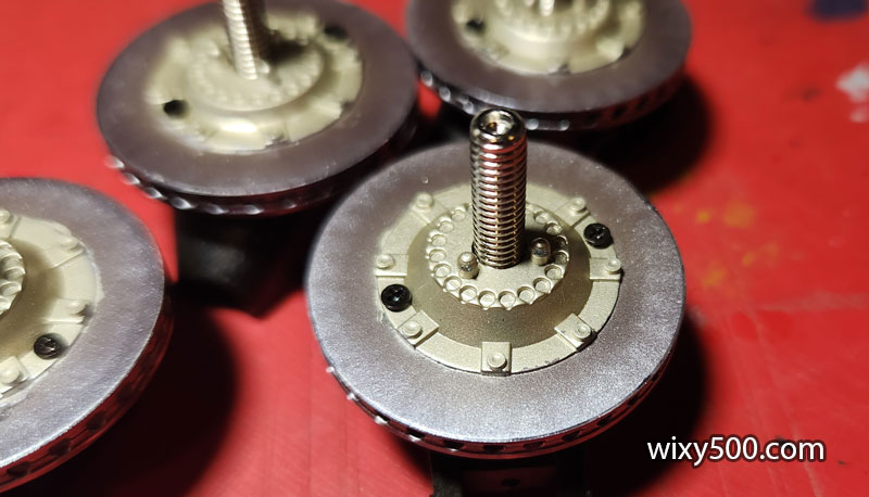
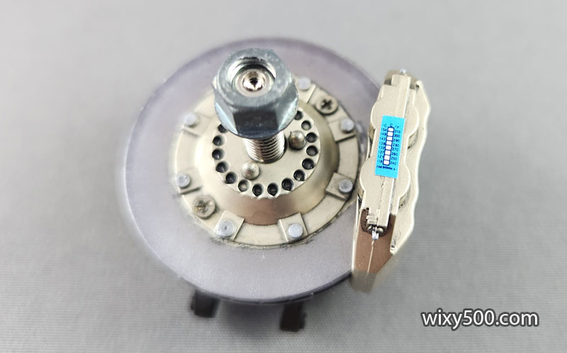
The two disc halves are screwed together with a nut held captive between the two. This allows the disc to be screwed onto the metal axle that’s mounted in the upright.
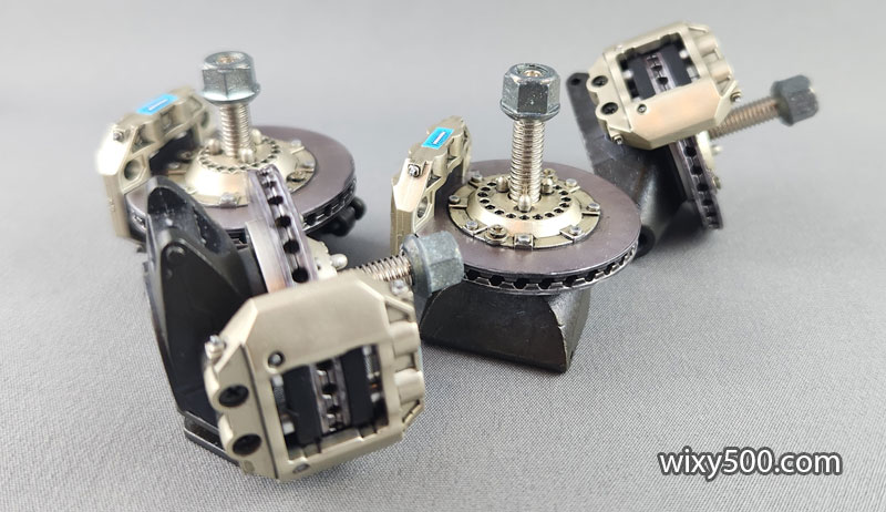
All four brake assemblies done! A dark wash was used in places to bring out the detail. Metal wheel nuts are fitted here so they don’t get lost.
Each calliper has a temperature-sensitive sticker so the mechanics can quickly check the max operating temp. After zooming into the photos I can confirm the tiny print is actually legible! (Though it appears the scale is wrong for brakes). Bolt heads and bleed nipples are painted silver.
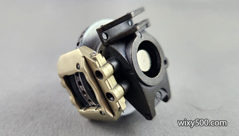
Callipers attach to the metal uprights via two 1.7x5mm screws, which sort of detract from the good looks of everything else, but that’s just how this kit is engineered to fit together.
Back of the upright will be covered over by the brake ducting, but otherwise, these assemblies are ready to attached to the suspension (once the suspension gets built).
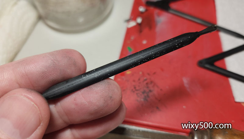
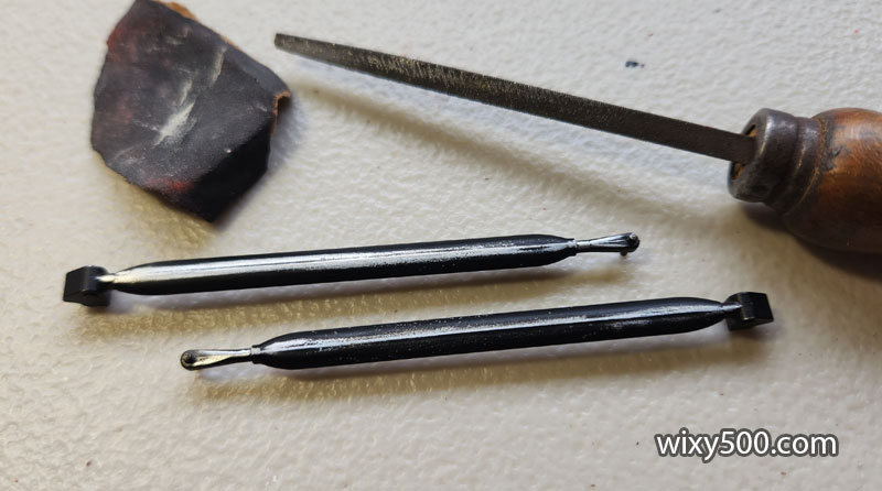
The upper surface of the front pushrods has this casting line all the way down the middle, plus weird speckles of missing paint (some of the parts in this kit are pre-painted from the factory, including all the suspension arms).
So I sanded and filed to smoothen it out ready, to re-paint.