I hadn’t built one of Tamiya’s big 1:12 scale models since I was a kid and this (along with a bunch of others!) had been sitting in the stash for far too many years.
The plan was an out-of-box build, but as usual, I ended up adding a few wires and pipes that were not in the kit. I also made a mistake in chassis assembly that had a lingering consequence through the rest of the build.
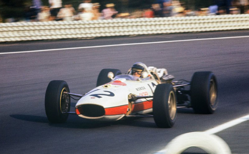
The RA273 was Honda’s answer to the new-for-1966 three-litre engine regulations. The Japanese company retained a V12 configuration, but switched from transversally mounted to the more traditional longitudinal position to fit the massive V12 into the car.
According to Autocourse’s “History of The Grand Prix Car 1966-85”, the RA273 was the largest and most powerful car in the field in 1966. Its thirsty (and physically big) engine required a huge fuel load (across 6 fuel tanks!) to get it to the end of a race.
It followed standard design principles of the time; cigar-shaped full-length aluminium monocoque, rocker-arm front suspension with inboard coil-over-shocks, double trailing-arms and outboard spring/shocks at the rear.
RA273, here driven by Richie Ginther (pic – Motorsport Images)
The Kit
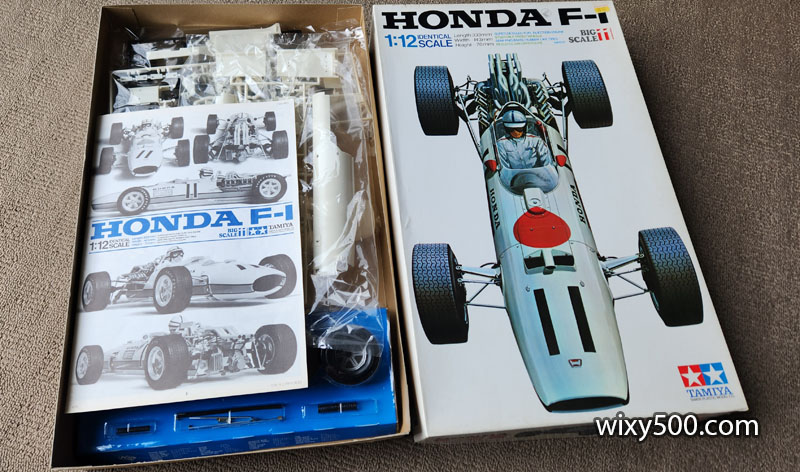
The kit is Tamiya #12011, number 11 in the company’s Big Scale Model Series. However, I’m confused about its age.
The Scalemates website says the original was released as kit #1 (item #12001) in 1967 and was re-released in 1973 (as kit #12011 – the number on this kit). A new version (kit #12032) was released in 2006 and included extra photo etch parts.
Tamiya kit #12011, number 11 in the Big Scale Model Series. Despite its age, everything appeared in good condition.
Kit content, moulded in body-colour off-white, grey/silver, black and clear sprues, plus plated parts, rubber tyres and metals springs. No photo etch in this one. The decals appeared fine and had a flat finish, but turned out to be unworkable.
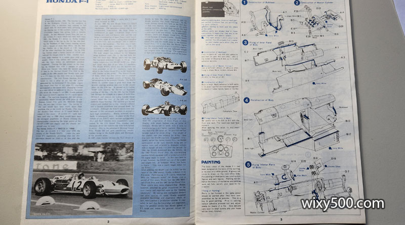
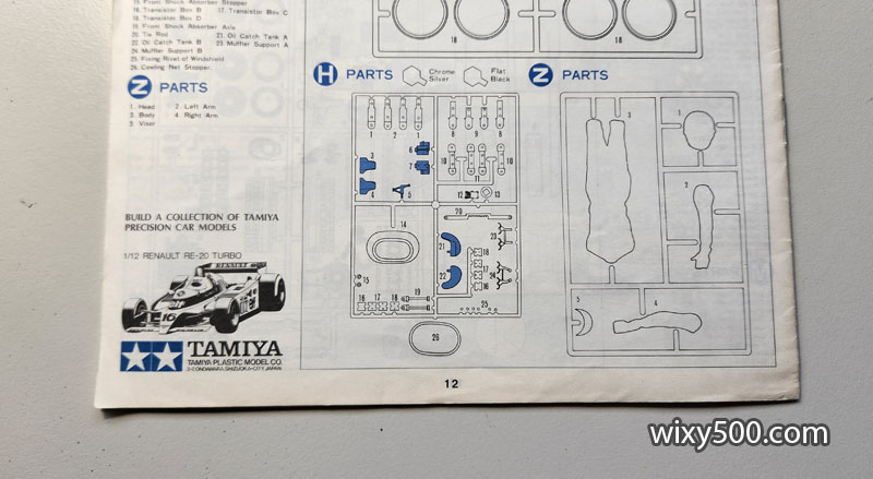
The instructions are the “old style” from Tamiya, showing where the glue needs to be applied with just basic colour call outs. The instructions in the later releases (available to download from Scalemates) have been totally re-designed. They are much clearer to follow and include all the Tamiya paint codes for the parts.
Despite these being the old format instructions, my particular kit could not have been released in 1973 – that’s a 1980 Renault illustrated in the corner!
The Build
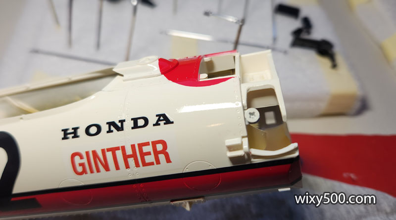
The car changed considerably from race to race with options and parts this kit simply does not include. I decided to not build to a specific race, but just a general representation of the car raced by the American driver Richie Ginther in 1966.
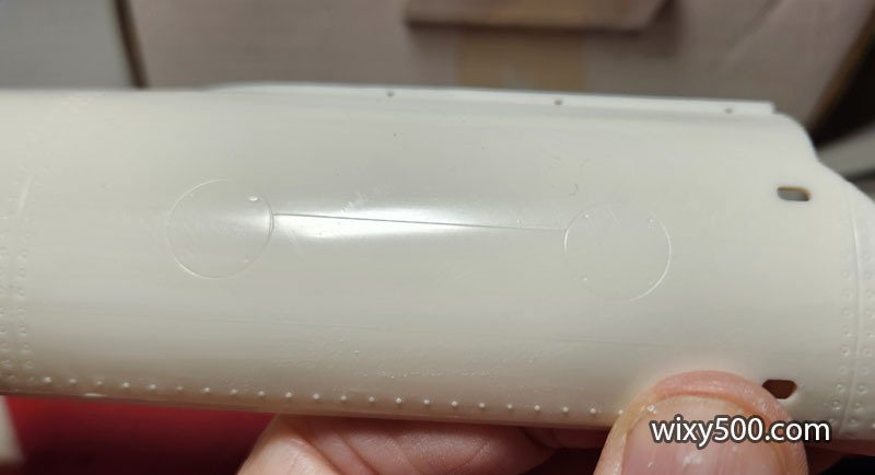
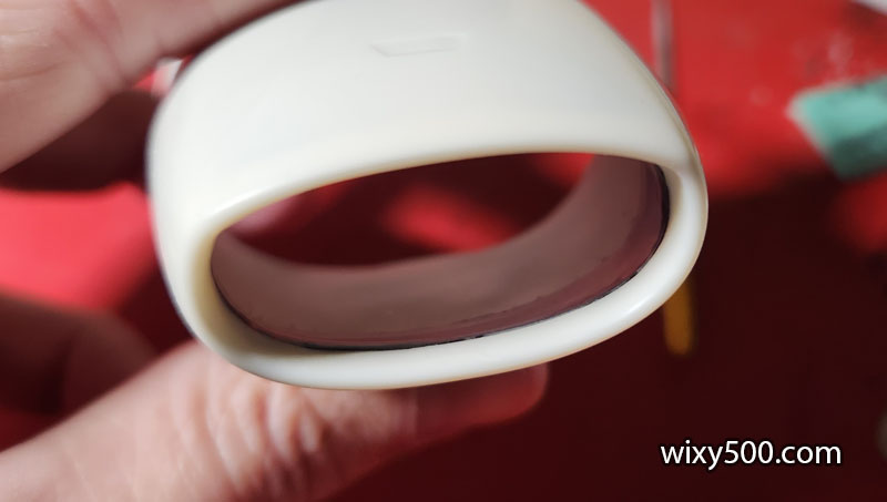
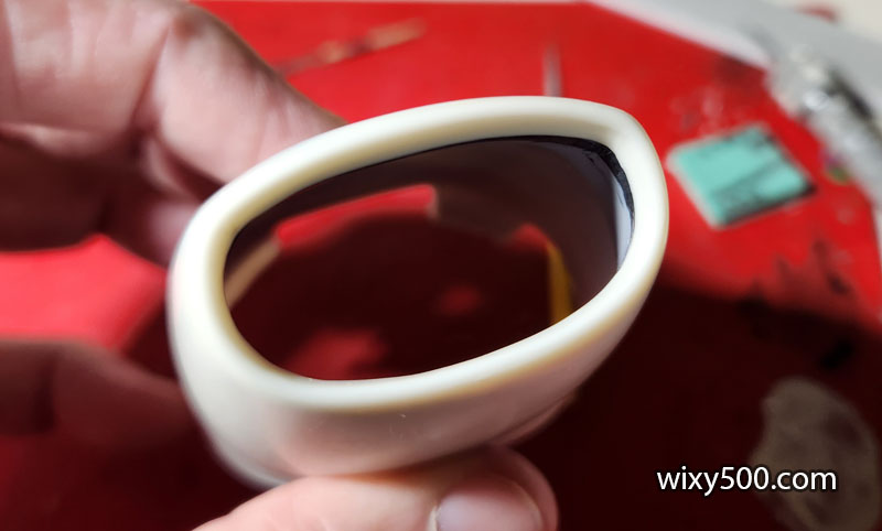
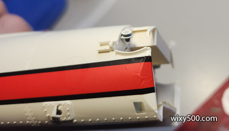
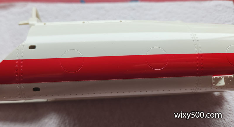
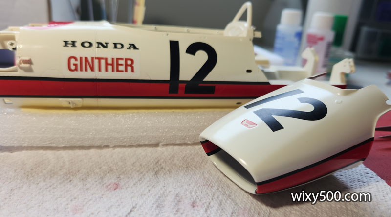
The fine horizontal line seen in the reflection is to align the big red decals later in the build. I didn’t want it this sharp so gave it a light sanding, being careful not to take off any of the other detail cast into the part.
Scribing some of the panel lines a little deeper, including the round access panel covers
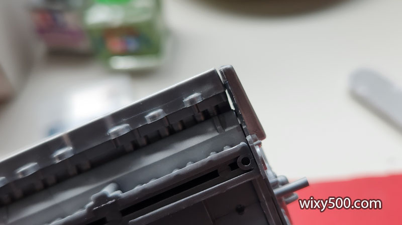
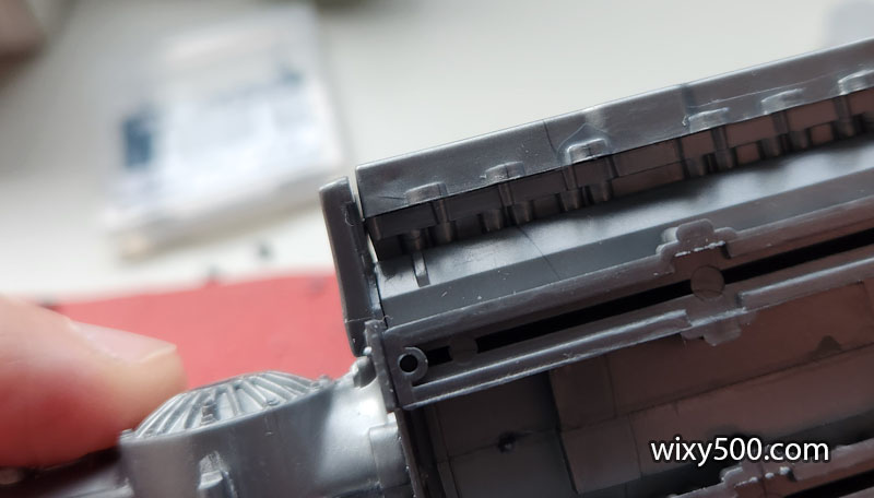
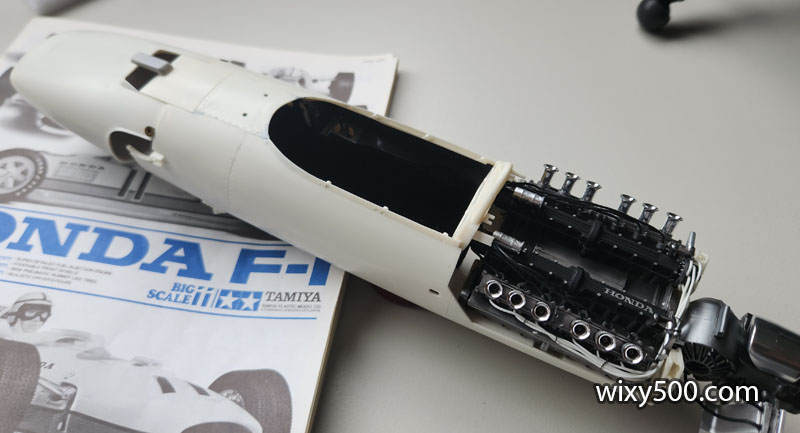
The fit on this old 1:12 is not as precise as modern Tamiya. There is a gap on each end between the cylinder head and the end piece of the engine assembly. Despite this, the engine block and gearbox go together easily.
I think to fill these gaps might make them stand out even more. The engine will be painted a dark metallic grey, so hopefully will not be too noticeable on the completed model.
The oil cooler scoop (left) and oil tank (right) are both multi-piece parts that are to be bright aluminium colour, so gaps and mold lines are smoothened out before paint.
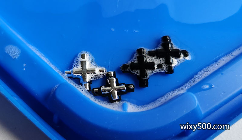
The four universal joint knuckles are part of the chrome plated sprue, but I can’t see in any reference material that supports this colour. A little bathroom cleaner strips the plating in seconds, revealing black plastic underneath (there’s a How-To video about this on my YouTube channel).
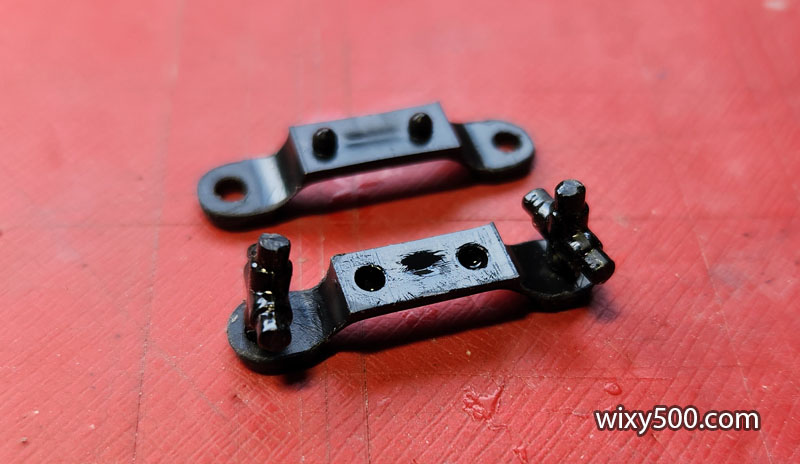
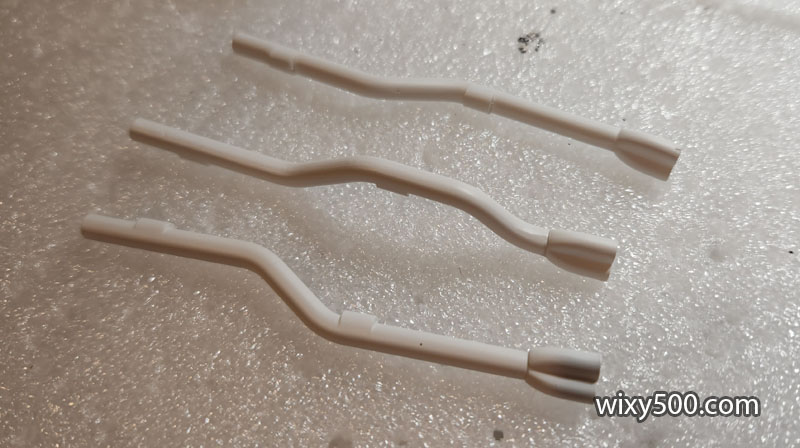
Drive shafts are made of eight pieces each. This is the middle section that clamps the universal cross joints in place. Important not to get glue on the two knuckles so they can rotate once assembled.
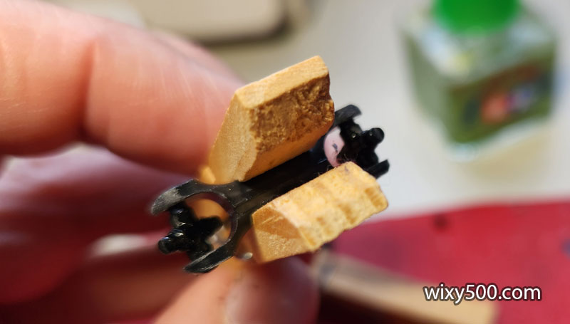
Wooden clothes pegs hold the halves together while the cement (Tamiya Extra Thin) sets.
Final stage of assembling the rear axle parts. Next is to scrape and sand the join marks in each shaft.
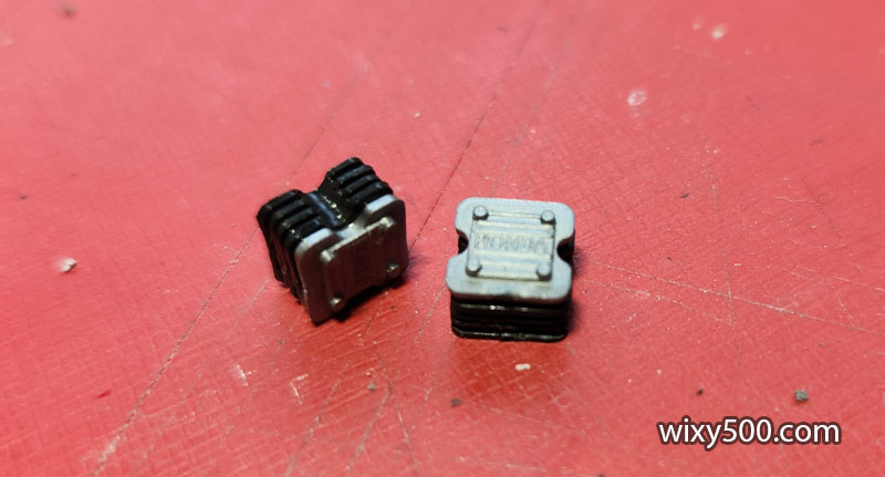
Each of the ignition modules comprises five pieces layered up like a sandwich
Various parts prepped (seam lines/flash removed, filler added where required) and awaiting primer.
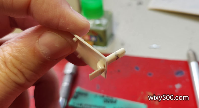
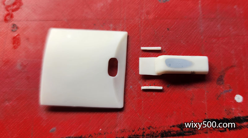
This small air scoop does not thread through the mounting hole like the instructions say it should.
So instead of inserting the tubular section, I decided to cut down the flat part, and feed that through in the opposite direction instead
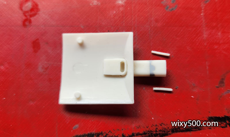
Cutting two small slivers off the sides narrow it down sufficiently.
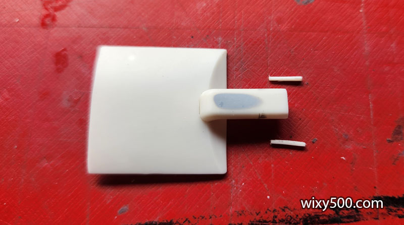
Perfect. The grey is filler/primer will hopefully hide a sink hole in the part.
Just needs a dab of cement to hold in place.
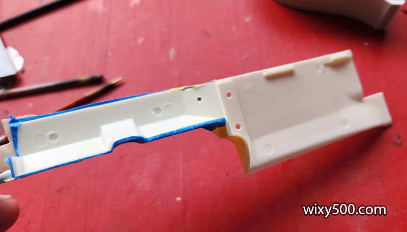
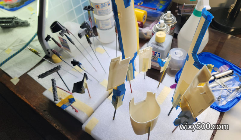
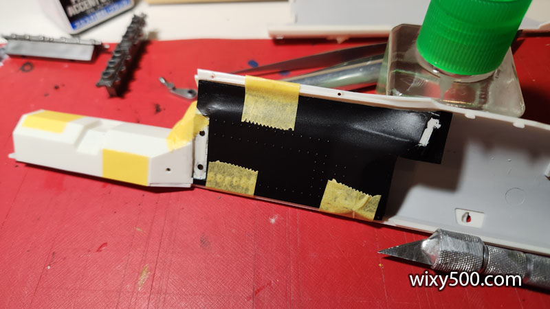
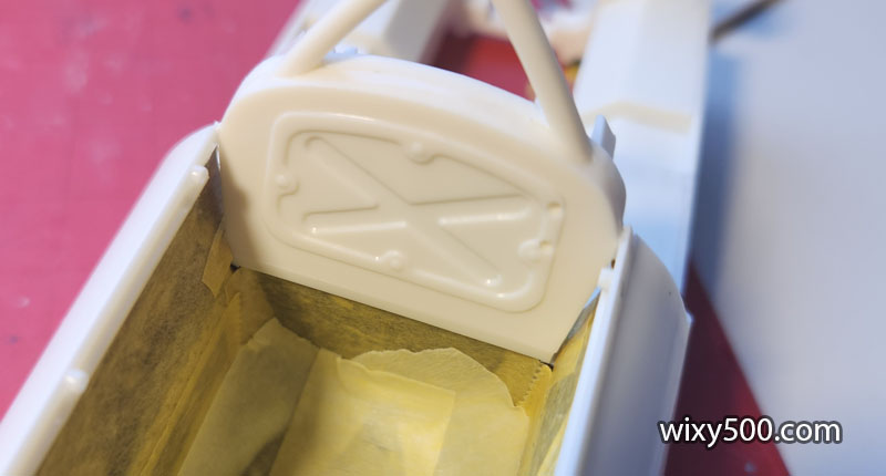
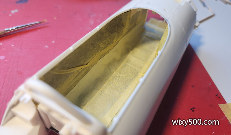
To reduce the translucency of the main chassis panels (you can see here the shadow cast by the tape as sunlight bleeds through), I decided to hit the insides with a coat of grey primer. First step is mask the edges and suspension holes so the grey primer can’t overspray to the outside surface, which will be done with white primer later in the build.
Same deal with the reverse side of the inner monocoque panels.
First paint for this build! A batch of Tamiya Grey Primer on and in several parts.
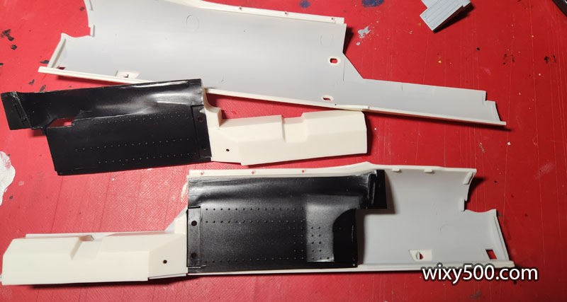
Masking removed from the chassis panels. The inside surfaces of the cockpit panels are in semi-gloss black
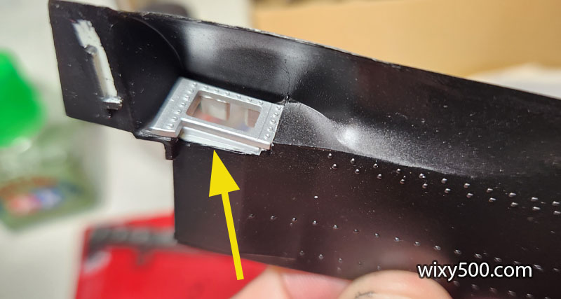
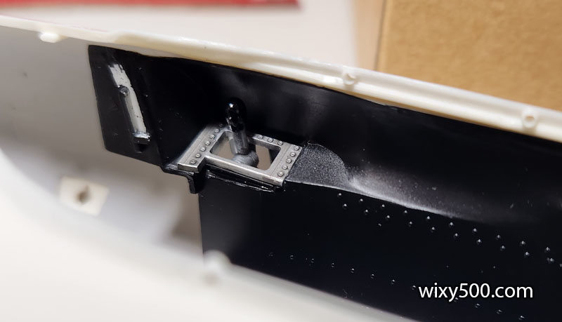
There was a gap between the gearshift surround and the monocoque, so I cut a piece of plastic to shape and glued it in.
This is how it came up after a bit of paint and wash on the rivets.
Tape holding the two parts together while the cement sets for the left side of the monocoque. Fit is not precise so I went around several times filling the gaps with extra glue. Rinse and repeat for the right side.
The main chassis pieces come together.
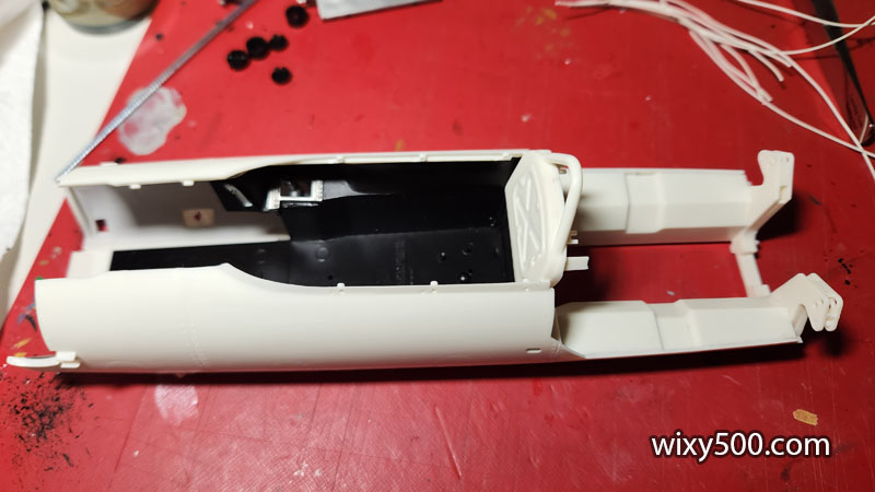
Underside of the first major chassis assembly step. There’s a bit of work I want to do on the interior before the second part of the floor goes in.
Engine bay. This is the raw plastic colour, but it’s pretty close to what the final colour will be.
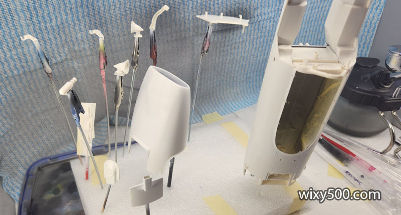
Various metal paints were used on engine parts. Some pieces have been primed (in either grey or black) and some haven’t.
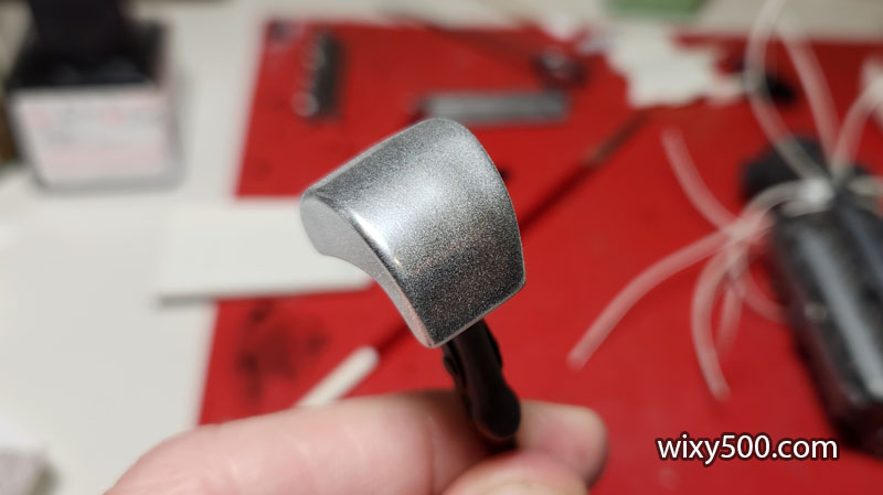
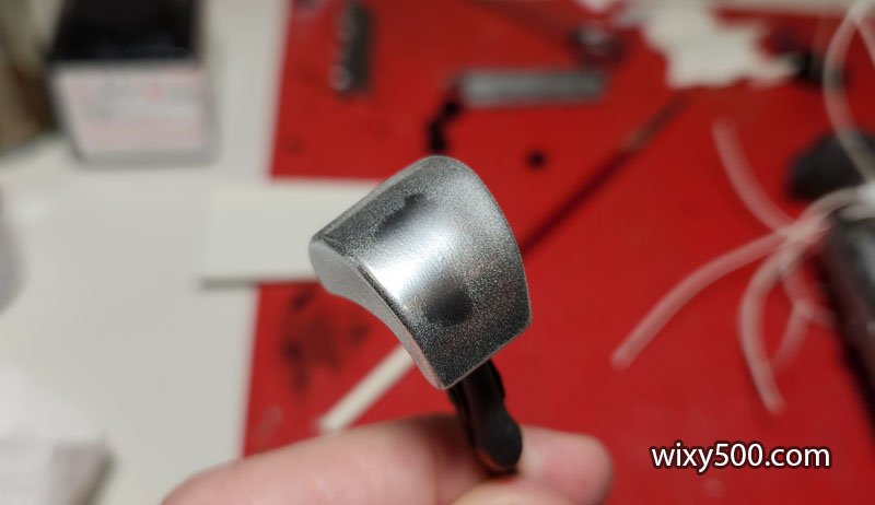
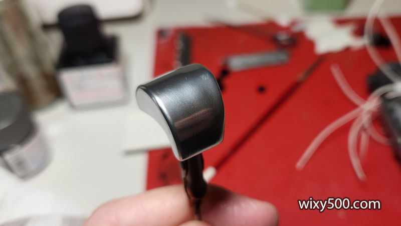
Another time using Alclad and another frosted finish. This time it’s Alclad’s polished Aluminum over gloss black.
I wiped a cotton bud across the part – it removes the frosty powder…
…revealing a polished aluminium effect.
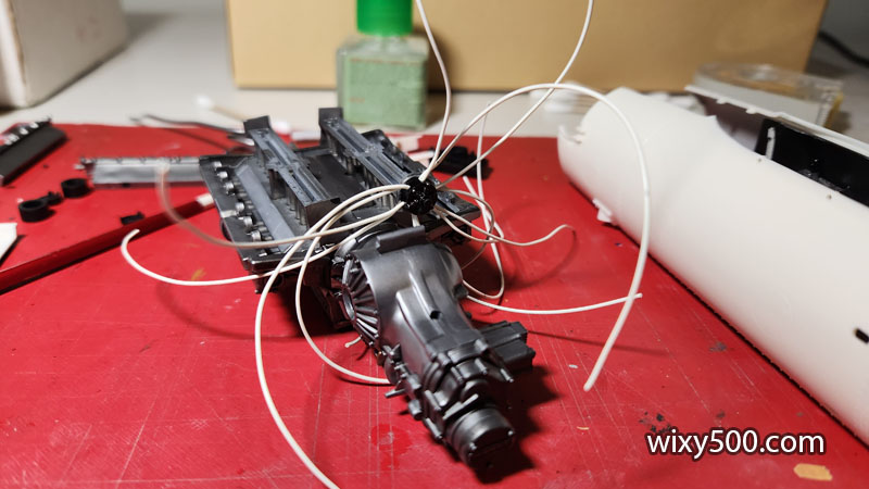
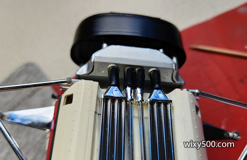
This is how the kit instructions show to assemble the fuel lines in the metering unit, but because they all cross over on top of each other, there is no room for the part to sit down on its mount on the engine. I re-routed the lines: as soon as a set of wires went into the unit, I looped them back out at the next exit (but I forgot to take a pic!).
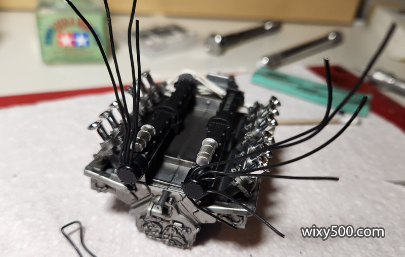
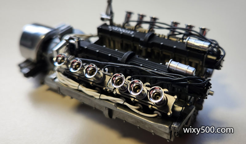
Looks like alien tentacles flailing about! Engine and gearbox have been done with SMS Steel colours, then Tamiya Panel Line Accent as a wash.
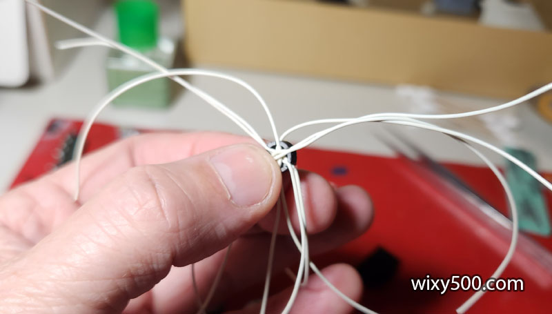
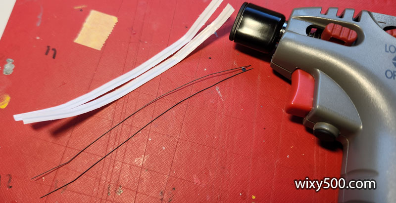
I wanted something to tie up the fuel lines and make them look a bit more organised. I know there are special in-scale model ties available, but I don’t want this to be an expensive build… So, I grabbed some freezer bag ties, burned the plastic off with my crème brûlée torch, then used the wire from inside – which was conveniently blackened from the heat! Win win 🙂
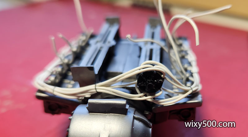
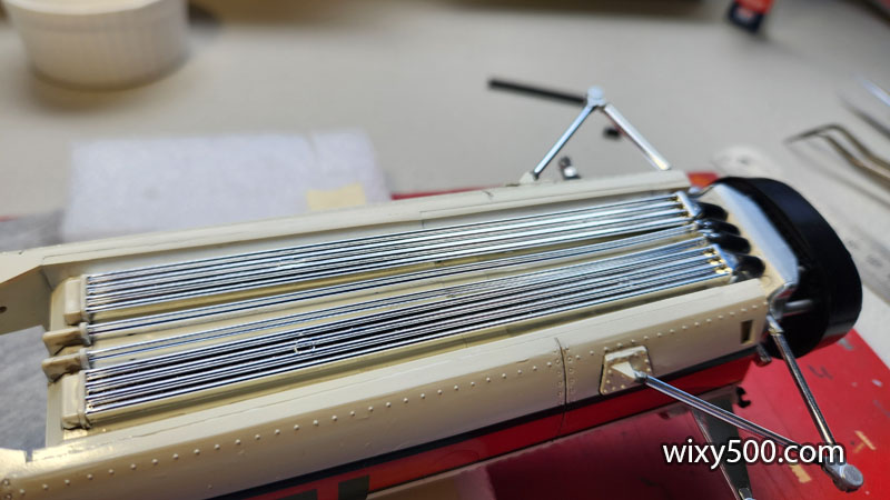
The instructions call for the intake banks to be in place prior to fitting the fuel line, however by leaving the banks off, it gave me room to manoeuvre each fuel line and more easily pull them through to get the length and look right.
Fuel lines plumbed. Now the excess can be trimmed off ready for the intake and injector banks to be glued in place. The wire ties were fiddly, but look ok.
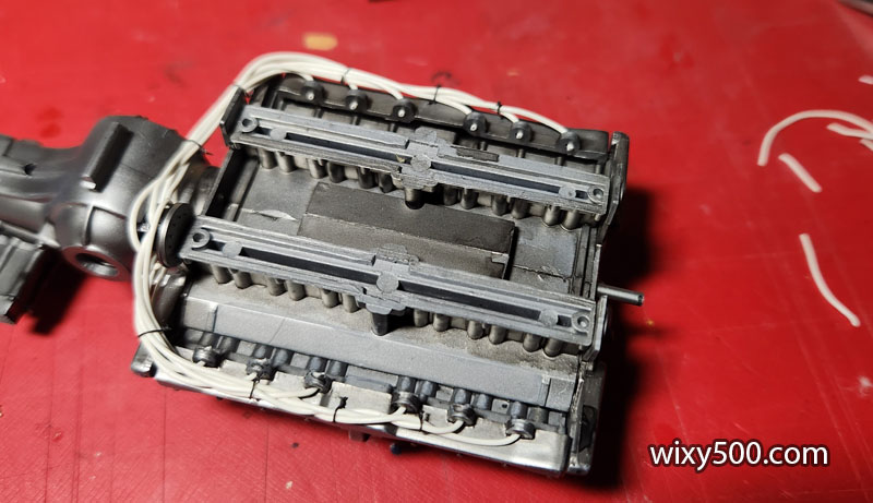
I have no idea or reference to which line-out from the metering unit went to which cylinder, but I’m happy with the overall effect. I debated about ‘yellowing’ the fuel line. On photos of the restored car as it stands today, the fuel lines are transparent yellow tube. On period photos, I’ve seen both clear/yellowed fuel line and white fuel line. So I just went with what came in the kit.
Fuel lines were secured in place with a little CA glue, then the excess wire clipped off.
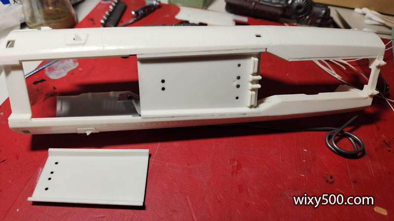
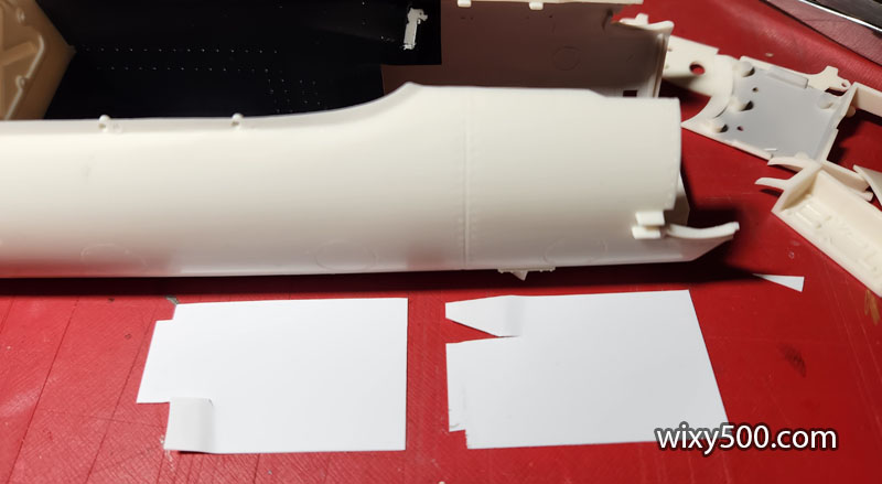
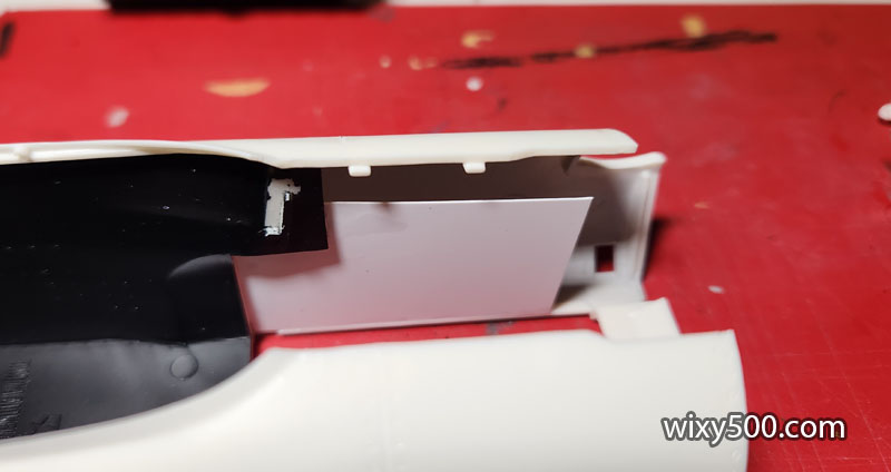
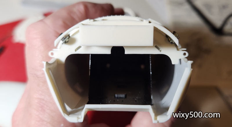
When the dashboard and scuttle are fixed in place later in the build, the vacant innards of inside the cockpit will still be slightly visible. So, to extend the inner skins of the monocoque, I cut up some Evergreen sheet, 30mm x 50mm for each side, and trimmed to fit.
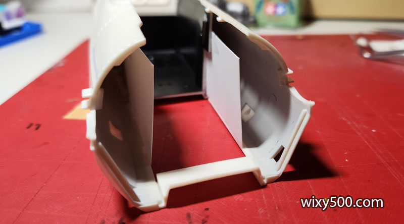
Left side test fit.
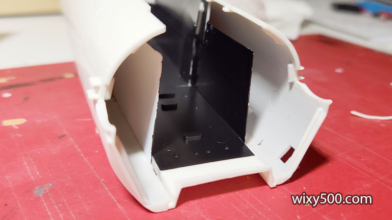
The inner skins do not need to go all the way to the front bulkhead as that area will not be visible once assembled (which I guess is also the reason there are no pedals included in this kit?). Just need some semi-gloss black on the new skins, then the rest of the floor can be glued in.
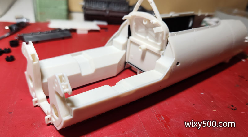
Now with the full floor and paint.
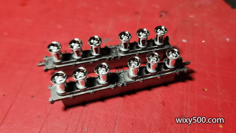
Fuel injection trumpets fitted to the throttle body slide. I decided to go with the plated parts as they are supplied in the kit.
Intakes fitted to the engine.
The later versions of this kit include metallic photo etch for the brake disc surfaces. Instead of leaving these surfaces smooth plastic, I scuffed radial scores into them with an emery board.
Hoping this will give a bit of a used effect once painted.
Another batch of parts drying in the paint booth, SMS Super Silver plus black (mix of flat and semi-gloss acrylic) on the valve covers.
Ignition distributors fitted. Now to run the plug leads where they need to go. Unfortunately, this is very unrealistic – the kit just uses small locating tabs with holes to hold the wires; they do not feed into spark plugs or combustion chambers. It’s similar with the fuel lines, they do not connect to the actual injection stacks. The two ignition coils (the silver canister on each bank) are glued in place, however I’m yet to find a reference for any wiring.
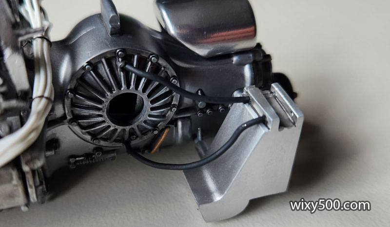
After the spark plug leads were all in place, I glued the transmission cooler and scoop to the side of the gearbox. The kit included no plumbing for this, so I drilled holes in the parts and inserted pieces of solder for the line in and line out.
The solder was then painted rubber black (Tamiya XF-85) to simulate rubber hose. Also, the polished aluminium tank above the gearbox has been fitted here.
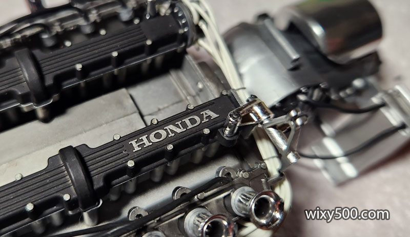
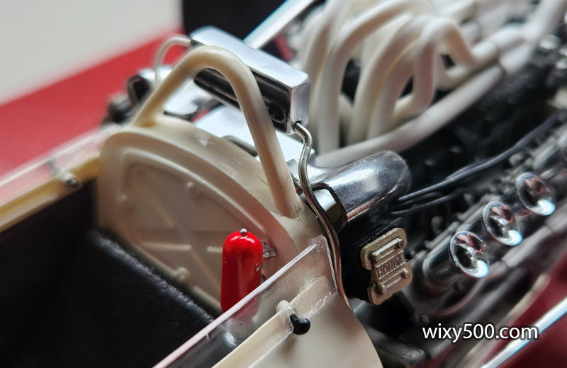
The valve covers were sprayed with black (a mix of Tamiya acrylic flat and semi-gloss), however this one with Honda cast into the part was first hit with SMS Super Silver. The black was then carefully wiped off with thinners to reveal the Honda lettering. Bolt heads are picked out with a dab of Metallic Grey.
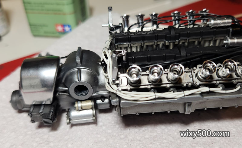
Starter motor sits under the right-side drive output.
Nothing more can be done on the engine until it’s installed in the chassis. The main job is the tangle of 12 exhaust pipes that will fit over the motor and into the central ‘V’. The kit instructions call for this to be done prior to installation, however I think it will be easier to fit them towards the end. Despite being 1:12 scale, the kit does not include a lot of the engine parts, and some of the bits that are included (eg some of the throttle linkage) is incomplete and does not fit properly. Spark plug leads (black) are all glued in place, but unlike the fuel lines (white) are not yet tied into bunches.
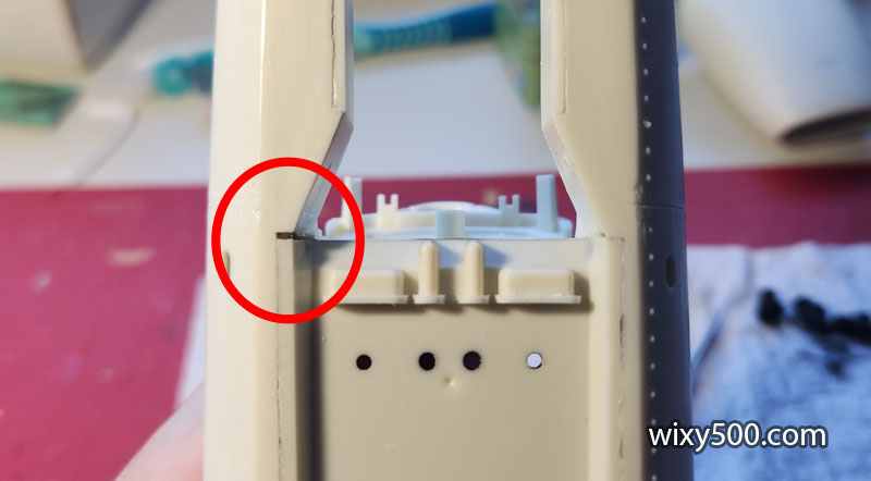
When I test fitted the scuttle (the top forward part of the cockpit) the fit was bad – it would not line up with the left or right body halves at the same time…
Closer inspection revealed one side of the monocoque had slipped back, making it out of square.
To somewhat fix the edge of the cockpit, I shaved some plastic off the high part and glued the offcut in the low part to try and get a more consistent radius. The windscreen will cover some of this, but it’s also possible the windscreen will now have its own fit issues.
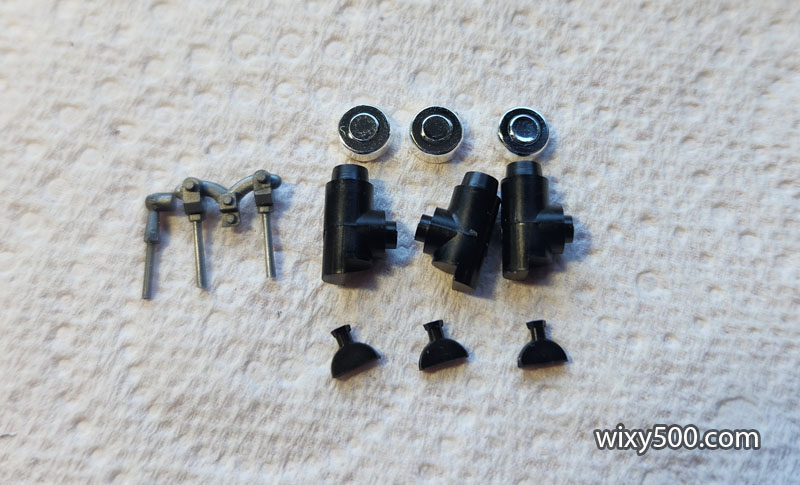
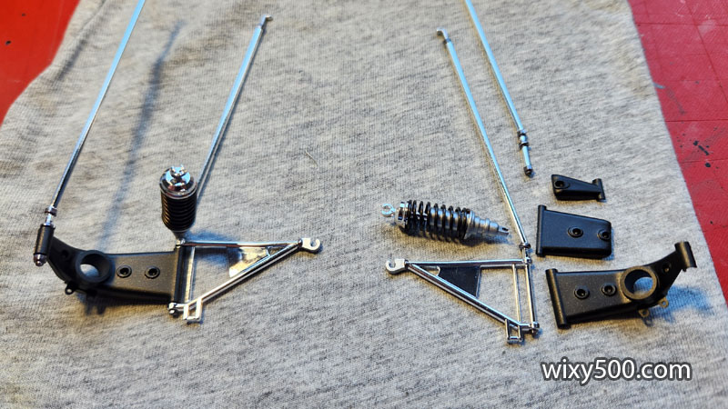
Brake and clutch cylinders and rods ready for assembly and paint.
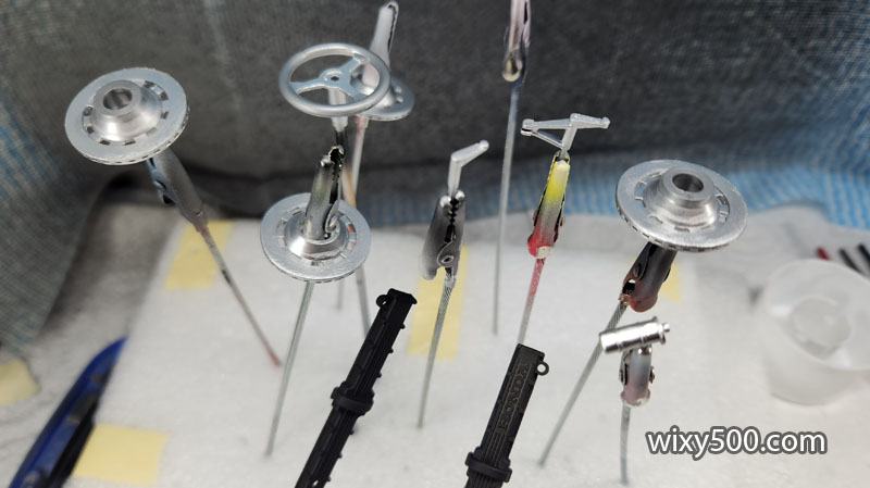
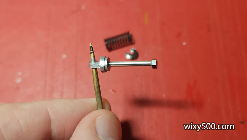
The model has working suspension which needs to be assembled. This is the front shock absorber shaft which has been painted chrome (Green Stuff World, with a brush).
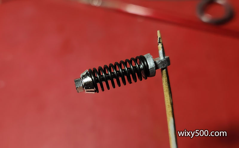
A plated clip holds the spring in place.
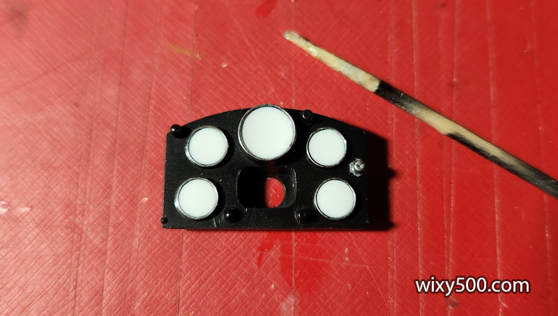
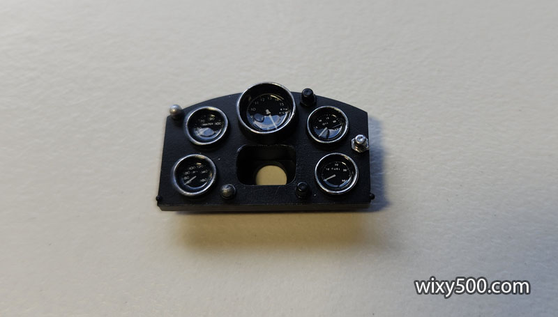
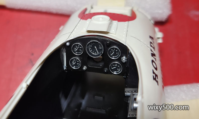
Dashboard has been sprayed semi-gloss black, then the decals applied for the gauge dials. Unfortunately the main tacho decal broke in the middle due to the recess having a hole in it (I should have filled the hole first). Chrome paint (Green Stuff World) was brushed around the rim of each gauge.
Kristal Klear was then dropped in each dial using a tooth pick. It’s white here, but dries clear.
Two days later, looks like glass.
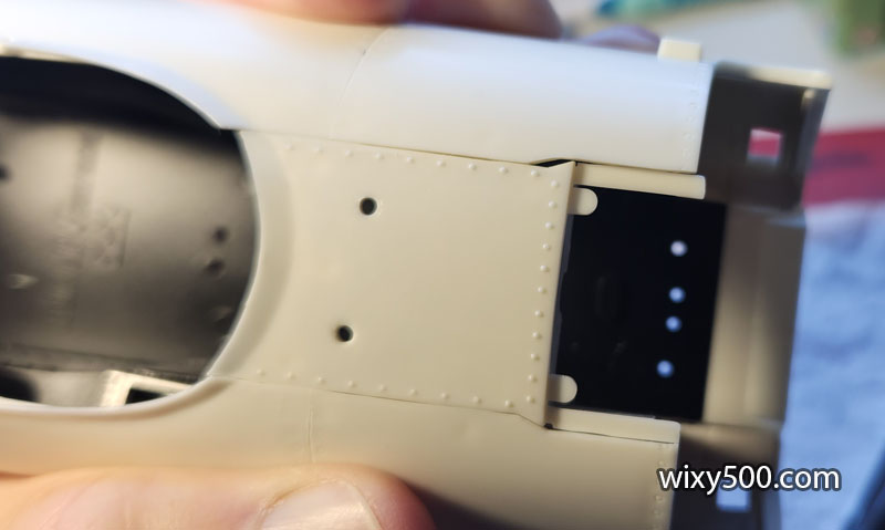
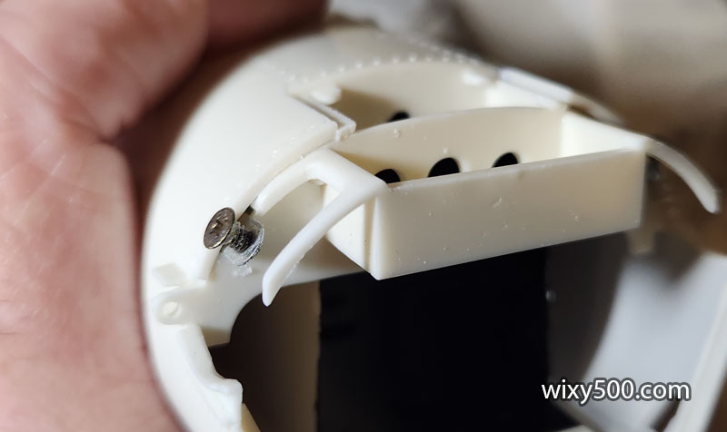
The nose locates on the plastic supports near the retaining screws (top of pic). I had to thin down the right side (left of photo, near the screw) to allow the nose to fit (compare to original thickness on right of pic).
Another view of the thinned down part. This problem is just a consequence of the chassis misalignment and the subsequent angle the front suspension parts take on.
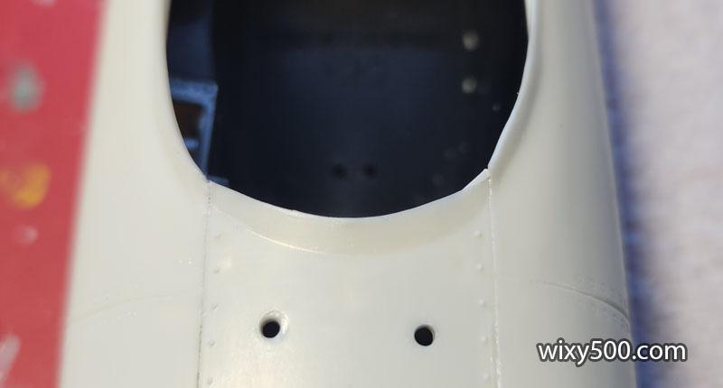
To help the nose sit straight, I also thinned and tapered the underside on one side.
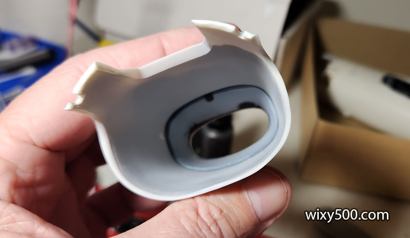
Compare the thickness of the material, left (stock) and right (modified). Also, the internal duct has been glued in.
The duct was was not a perfect fit, so this lower edge in particular had to be smoothed out.
But all looks ok, ready for primer.
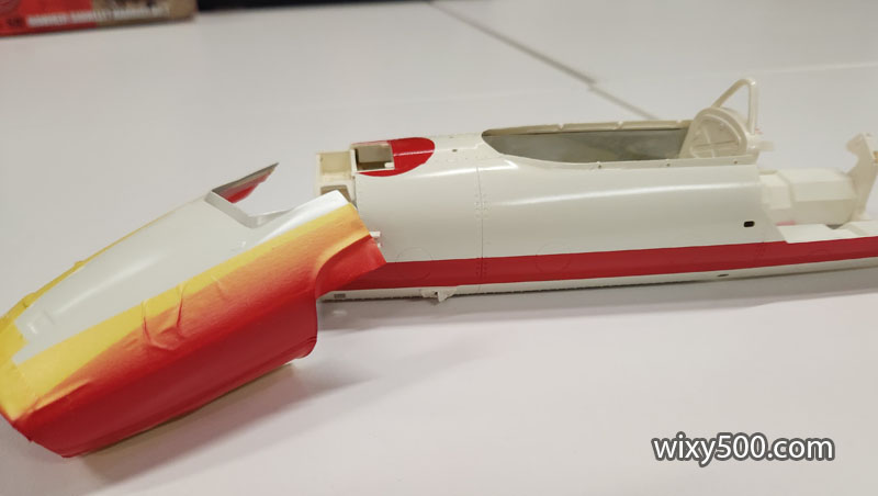
Mock-up with nose and engine sitting in place.
(Above & below) There are some pretty big gaps on parts of this model, such as between the rear bulkhead and the inner cockpit skins. I’ve masked the side of these gaps ready for body colour.
Tape down the entire length of the cockpit to keep the body colour out.
Tamiya putty filled and sanded in various locations, trying to hide the alignment issues.
A couple of coats of white primer on all the body parts.
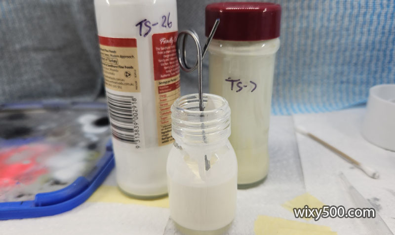
The kit calls for Tamiya TS-7 ‘Racing White’ for the main body colour, but I feel it’s too yellow. I’ve seen photos of some great builds where they’ve used plain white, but the real car was not stark white. So, I mix in some TS-26 Pure White to lighten up the TS-7. It must be the lighting in the photo playing tricks, but the custom mix in the small bottle is darker than it appears here, about half way between the two.
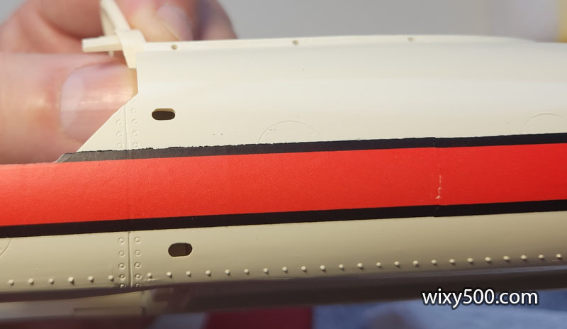
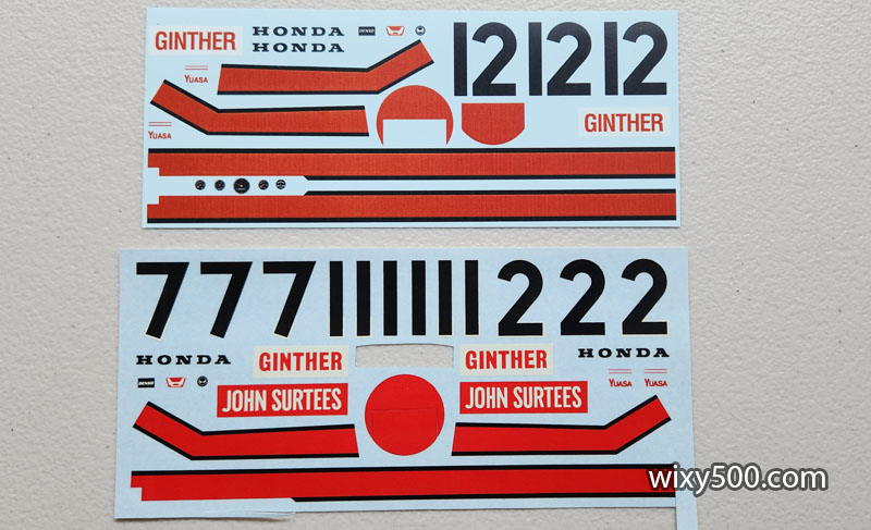
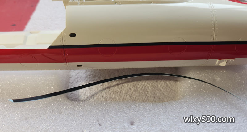
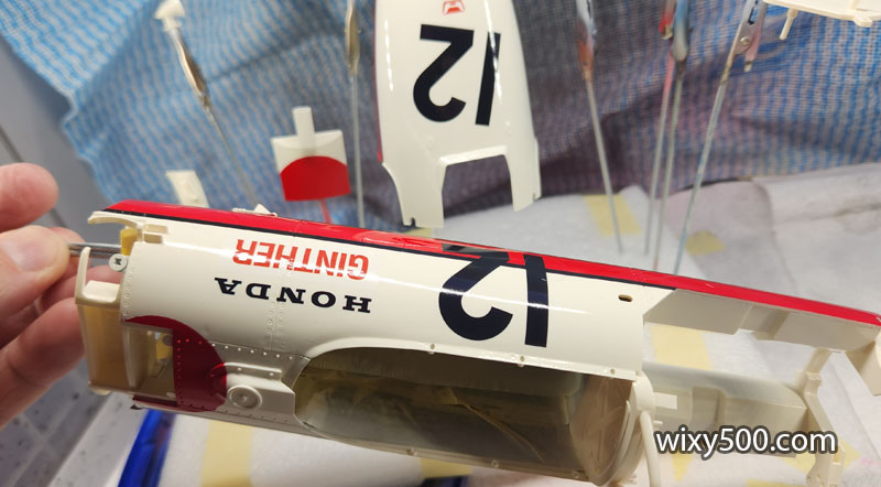
The kit decals are rubbish. The edges frayed (note the top of the black stripe), they are very stiff and won’t contour into crevices (note the lack of crease over the rivets and panel line) and they break easily. Normally a break can be hidden if properly re-aligned, but the edges of this break just started crumbling apart.
No matter how much softener was used, the decal would not stretch to go around corners without creasing. I even cut the decal to try and fold it down like the end of a parcel. So, an order was placed for aftermarket replacements from overseas…
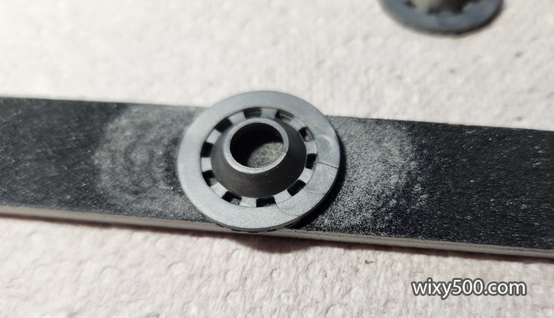
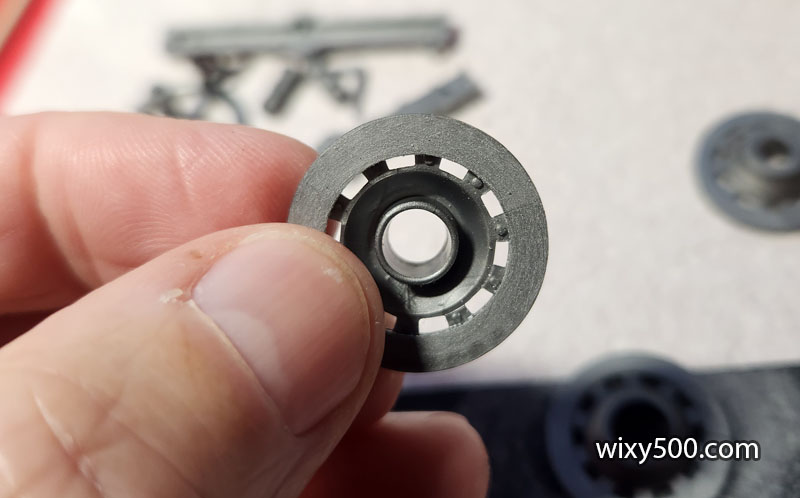
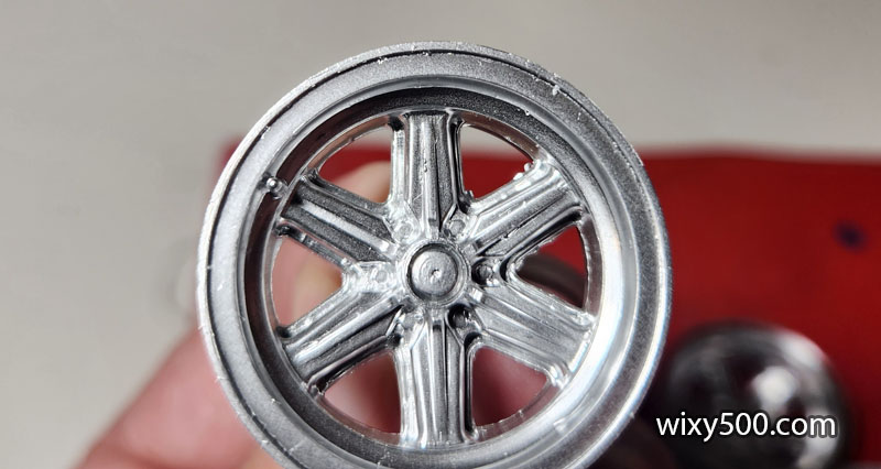
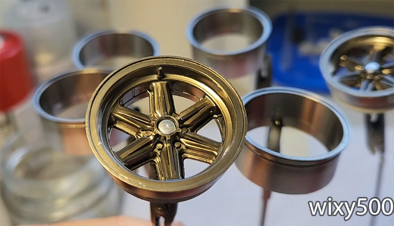
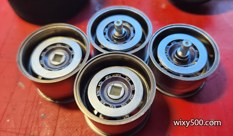
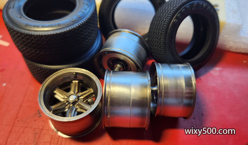
On to the wheels. A couple of the rims had some flash on the inside of the spokes that had to be removed.
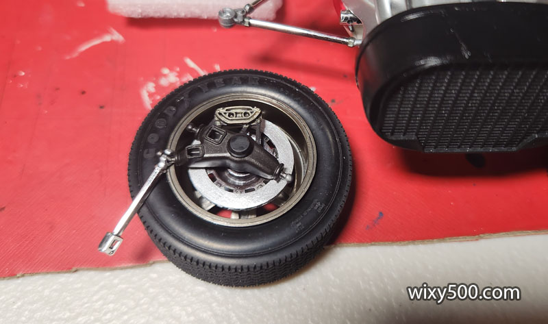
The plating was retained and the wheels hit with three coats of Clear Smoke to give a magnesium metallic look. Centre hub was painted silver. Wheels are two-piece, the outer rim with wheel spokes, then an inner rim that glues to the back. The wheel nuts need to be painted and a wash applied to the detail. Note the representation of a tyre valve cast into the rim.
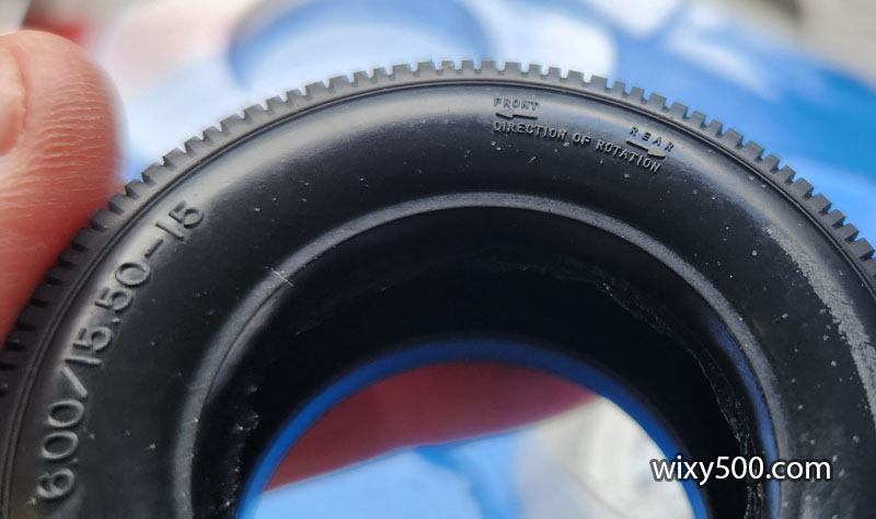
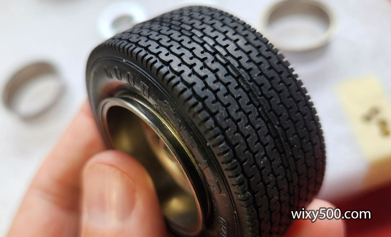
Tyres have fine markings in the sidewall for size and direction
The tread surface is really nicely cast, though there is a mould line up the middle that needs to be sanded off. Of far bigger concern is the tyre does not fit out to the full width of the rim!
There was a membrane of flash on the inside. I removed this in case it was preventing the bead from popping out on the rim properly, but it was not the problem.
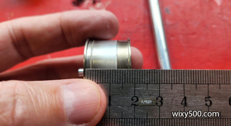
Upon measuring the rim width compared to the bead width of the tyre, there is a mis-match of several millimetres…
Exactly the same problem on the front. I considered cutting down the rim to make the wheel itself narrower to fit the tyre, however that would mean the upright/hub/brakes would protrude too far from inside the wheel and look really weird.
Next issue with this kit – no brake callipers! (the upright added later in the build does have part of a calliper cast into it, but it looks terrible)
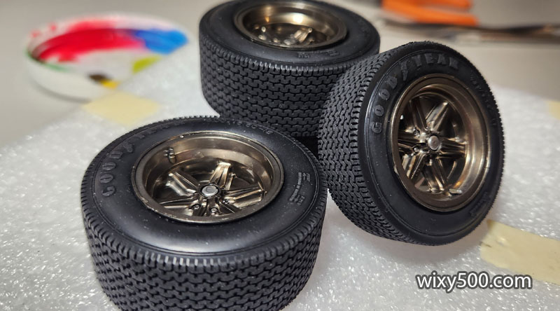
With the inaccuracies adding up and motivation for this build starting to wane, I decided to just go with how the kit was produced. The two rim halves are glued together for each wheel and the brake discs glued inside those. The tyres have been sanded and are ready for fitting.
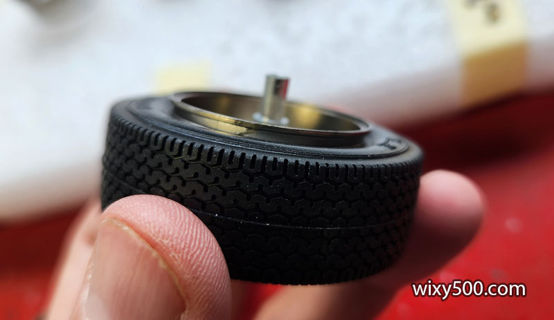
Once the rubber was fitted I massaged the tyres to try and spread the sidewalls further outwards. It might have helped a bit, but still doesn’t look quite right.
As per earlier pic, the original kit decals (bottom) were no good so I ordered some after-market items from a decal maker in the USA. I was disappointed when they arrived (top). To my eyes, the colour was way off (brownish-red) and there was what I’d call a ‘printer grain’ through them (difficult to see in the photo).
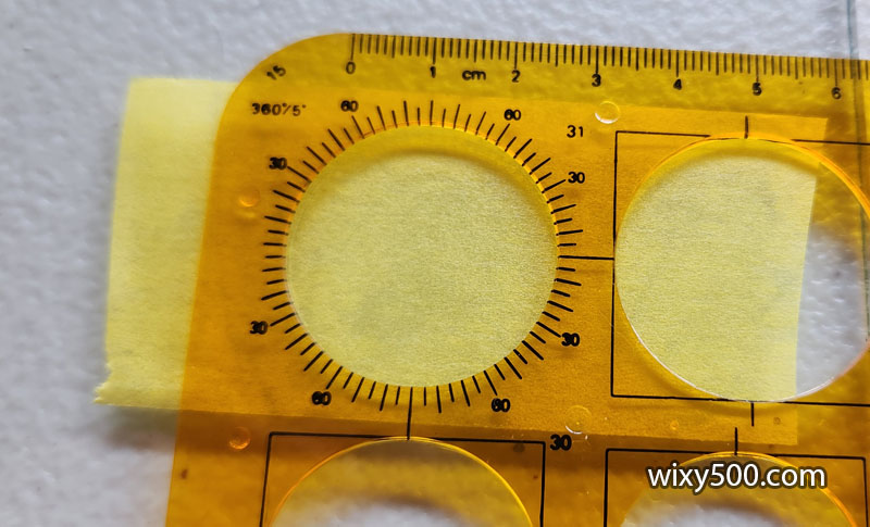
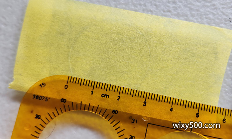
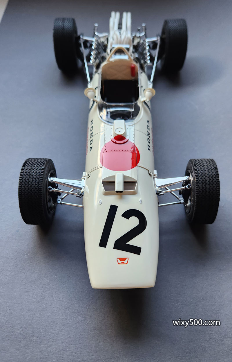
With unsuitable decals for the red, it was time to create some masks to paint the red bits. The car has a red circle on the scuttle to represent the Japanese flag. I used this circle thingy to create a mask from Tamiya’s wide 40mm masking tape that’s been laid down on some glass.
Once the circle is cut, the outer piece of tape can be lifted off and applied to the model.
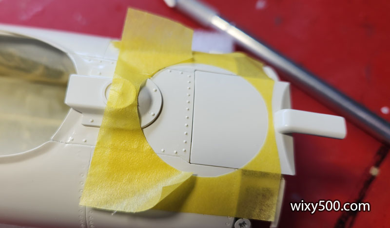
The removable scoop panel (bottom of pic) needs to be in place to ensure it also gets paint in the right spot.
The backwards facing venting duct also needs some red on it.
So a second circular mask was cut for that. The mask is just loosely in position here but the scoop was removed and the mask burnished down properly prior to paint.
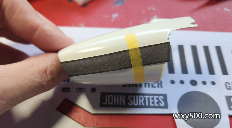
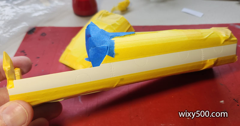
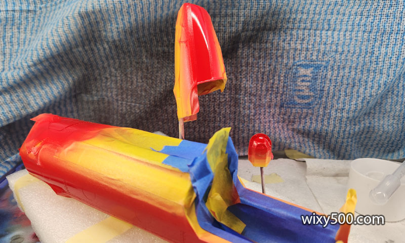
A photocopy of the kit decals is used to give a guide to where the paint mask needs to go on the nosecone.
The mask edges are then applied.
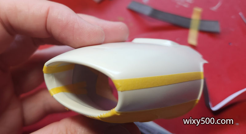
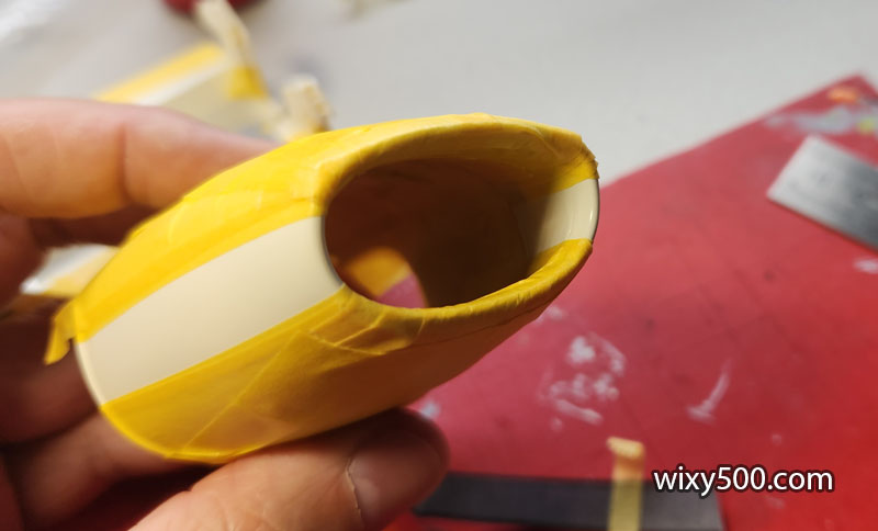
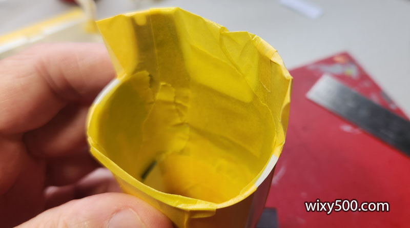
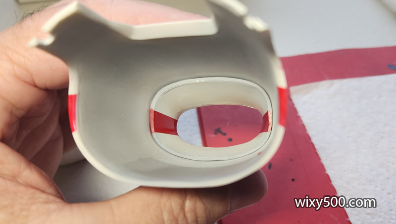
Then the rest of the nose covered. Note the red banner does not stop at the tip of the nose, but wraps back inside the duct towards the radiator.
So the internals also need to be covered up.
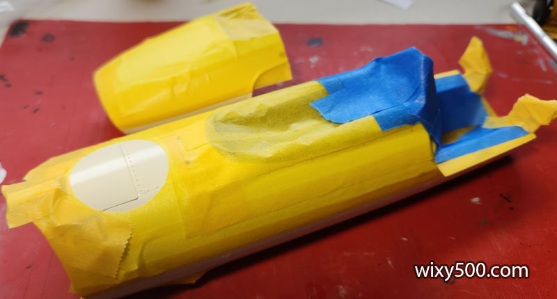
The rest of the model is masked up.
Now ready for red.
The red is Tamiya TS-8, Italian Red. Colour was built up very slowly with a couple of mist coats, then a couple of light coats. About 10 minutes later another light coat, then a final heavier application to get some gloss happening.
Part way through unmasking.
After masking is removed, a light wet-sand is required to take the paint edges off, the one at the bottom quite prominent.
Paint finish wasn’t too bad straight out of the airbrush. There is a small bleed (top left) but that gets covered with a black stripe.
The mask tape on the uneven surfaces did not give a great seal (or the cut edge was not clean) so there was some bleed through on the red circle, especially on the reverse duct which also had red over-spray beside the rivet.
After very light wet-sanding and some polishing compound it’s better than what it was, but not overly impressive.
Inside the nose cone after masking removed.
Painting the black stripes was considered, but I elected to carefully cut the black bits off the after-market decals and apply those. They are a little too wide, but I was afraid if I cut into the inked area any further, the colour might start to lift off the decal film.
When applying long thin decals, I lay the decal & backing paper on the model, then use a tooth pick or wet finger to push the decal off the edge of the paper. You don’t want to pull the paper length ways from under the decal as the surface friction can be strong enough to break it.
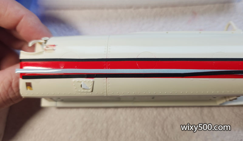
Top and bottom stripes applied with some softener around the panel lines and rivets to get the decal to sink in to the recesses.
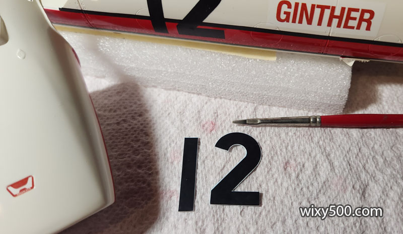
Rather than just cutting out the number 12, I cut around each digit and applied them separately so there was no section of clear film between them.
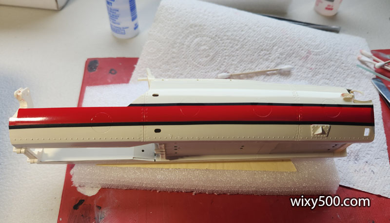
Decals done! While the colour was off, the after market decals went down well and contoured to the body with ease. Decals were left to dry for a few days.
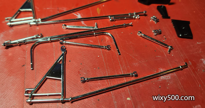
Lots of chrome suspension parts cut off the sprue. I decided to not strip the plating.
After the sprue gates were cleaned up, they received a dab of Green Stuff World chrome paint to somewhat hide the bare plastic. Fittings on the ends of the arms have been brush painted in various metallic colours to provide some contrast.
Clear coat done. The reason for clear on this one is more to seal the decals than to give a lustrous glass-like finish.
The bodywork got four coats of Mr Colour Premium Top Coat clear gloss in one sitting. This is how it came out of the airbrush. I elected not to polish as period photos of the real car show it to be not overly shiny.
After the bodywork painting was complete, the cockpit masking can come off. Thankfully, there were no bleed throughs!
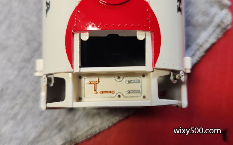
The instructions called for the brake master cylinders etc to be fitted to this double bulkhead prior to fitting to the chassis (it does not act as a bulkhead in the model, but it will support the upper suspension rockers later). I decided to fit the bulkhead first so that it could be glued and painted chassis colour all at the same time, then fit the parts afterwards. I started by brush painting some of the raised cast detail in copper and aluminium colour.
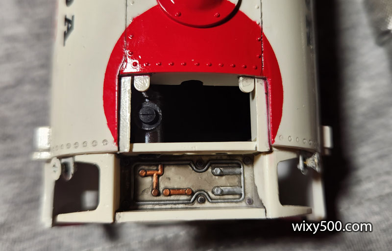
Then added some wash. The first of the brake master cylinders has been fitted here. It’s a really tight fit manoeuvring the parts into the available space – now I know why this was to have been assembled prior!
I had to cut an angled piece off the bottom rear edge of the remaining master cylinders so they had enough clearance to be guided in. Once in the model, it cannot be noticed.
Once all the reservoirs were in place the actuating rods were fitted (had to be cut down to slip them in, but the ends are hidden anyway) and wash added to everything to tone it down and bring out the detail.
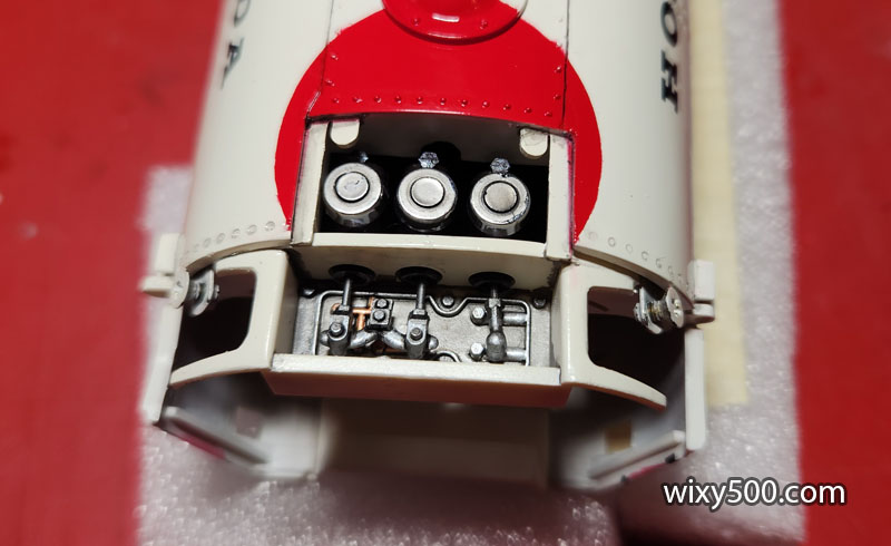
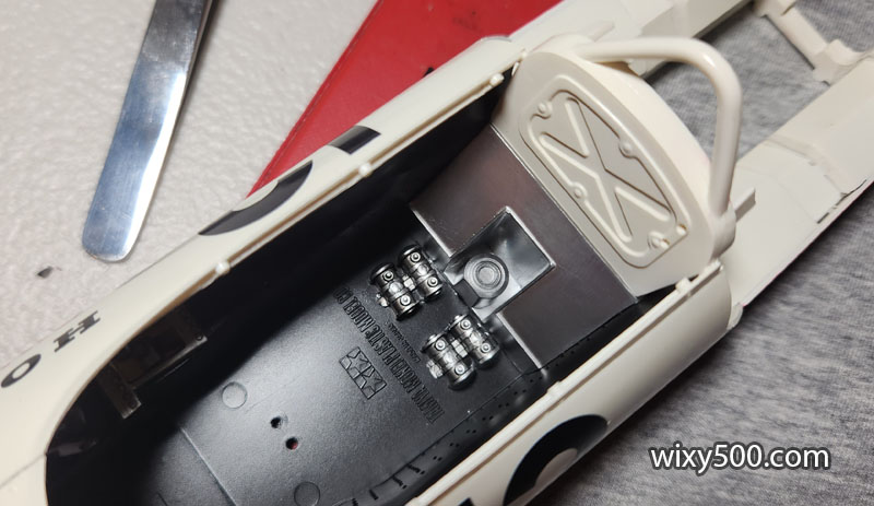
Fuel pumps and firewall drop in easily. I didn’t bother removing the Tamiya branding as all of this is hidden once the seat drops in.
Dashboard glued in, but there’s a huge gap down the left side. It was easily hidden with some semi-gloss black paint.
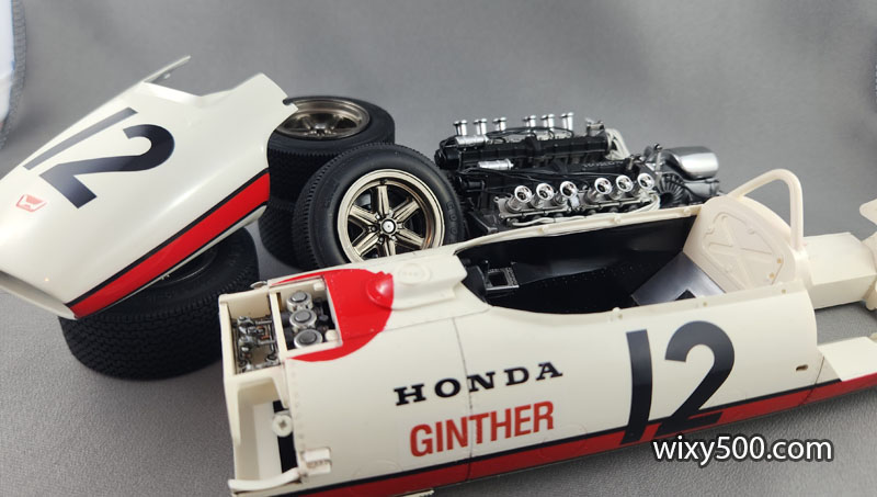
The main parts, waiting for final assembly.
Bulkhead glued in place, but it’s not a good fit (see following pic). It is a very fiddly exercise to get the bulkhead in position and at the same time get the spring units in position plus line the top rocker arms up in their mounts and clip the springs to the rockers.
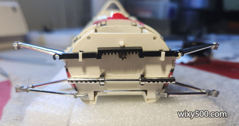
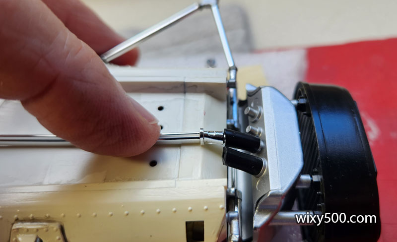
Lower wishbones easily clip in. Next step is to install a large tank that covers most of this, but the steering shaft and pinion could still fall out, so the steering wheel needs to be fitted on the other end of the shaft to secure it all.
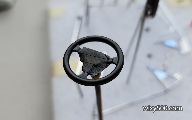
Steering wheel was painted silver (Tamiya LP-72) then masked and sprayed Semi-Gloss Black (Tamiya LP-5)
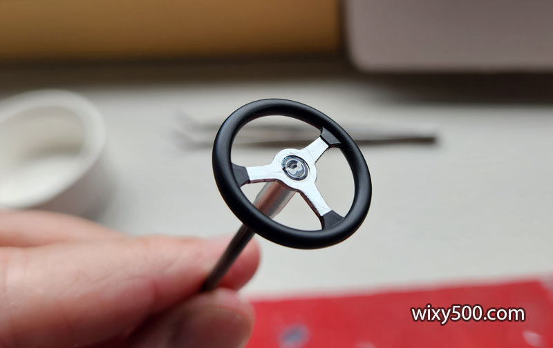
This is how it came up after the masking was removed and small Honda logo decal applied. It was then fixed to the metal steering shaft with a little CA glue.
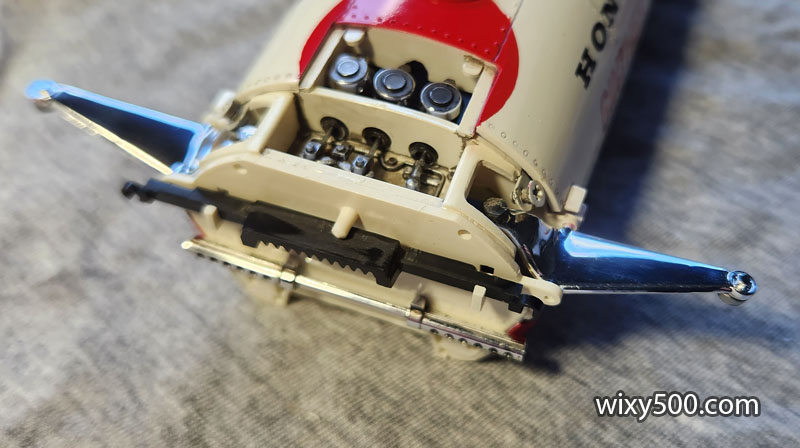
Black radiator glued to aluminium fuel tank glued to front bulkhead with a couple of support struts.
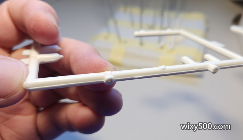
Coolant pipes run under the car from engine to radiator and back. Tamiya supplies rubber hose to connect these, but the tube is not really flexible enough for the job, so I cut each of the pieces at a small angle so there’s less pressure on the parts due to the bend.
It’s a tight fit under the nose of the car. I had to shave down the sides of several of these parts to make them narrow enough to all fit.
I didn’t bother to strip the chrome and they received a lot of panel line wash after this photo to dull them down. Not that they’re visible when the model is on display.
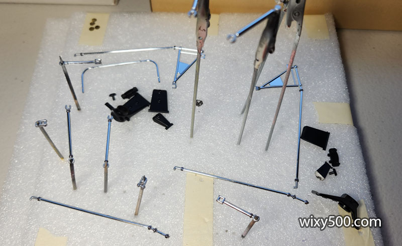
The suspension arms are mostly interchangeable left to right, but the upright components are not. Right side of pic shows various parts prior to assembly, left of pic is assembled and ready to clip onto the model. Uprights front and rear were sprayed a mix of semi-gloss black (LP-5) with a few drops of Light Gun Metal (LP-20).
Rear suspension and springs clip on to the back of the chassis. Trailing arms require the chassis pickup points to be glued on. These don’t bare any significant load, so I glued them with Kristal Klear to prevent damage to the paint.
The engine drops in with ample clearance, then the drive shafts can be fitted. Interestingly, no cement is required to secure the engine, the assembly effectively getting clamped down by a rear bulkhead brace in a later step.
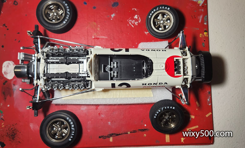
Goodyear lettering moulded into the tyre was brush painted by hand in flat white (Tamiya LP-4). This is time consuming and drives me nuts, so I only did the outer sidewalls. After the paint is dry I used a hobby knife to scrape off a couple of the overspills seen here. Crazy fact: the font used on the front tyres is slightly different to that used on the rear.
Front uprights have a rudimentary half brake calliper cast in. I painted this Titanium (TS-87, applied with a brush – not recommended!) then splashed some wash on it.
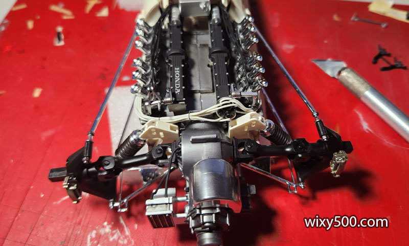
Engine is secure and the rest of the rear suspension is clipped on. Now ready for the wheels.
Rear wheels glue directly onto the rear axles. The fronts (which are glued to the upright via a pin so the wheel still rotates) simply clip into the upper and lower ball joints. Unfortunately, the upper-right fitting on my model is too loose to retain the upright. Care must be taken moving the model as the right-front falls out of it :/
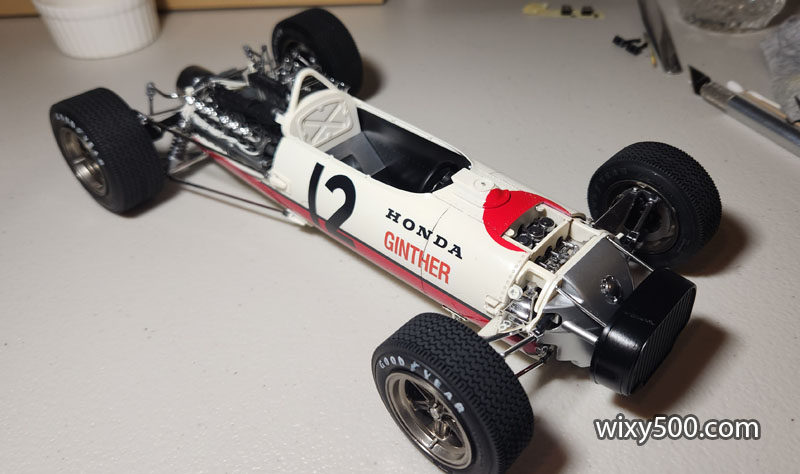
It’s not finished, but I had to pop the bodywork on, just to see how things will look 🙂
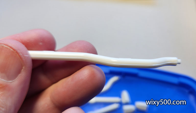
I wonder if the moulds for the exhaust pipe sprue have seen a lot of work because there’s quite a misalignment and even some flash which is unusual for a Tamiya kit.
Every piece had heavy mould lines. This is one of the main tail pipes.
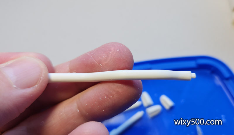
Scraping with a hobby knife cleaned most of it up sufficiently.
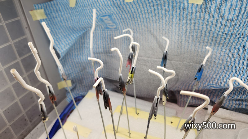
All 12 header pipes are unique. To prevent getting them mixed up during prep and painting, I write the part number for each on a foam block, put each part in an alligator clip then mount to the block in its numbered location. I can then pull a piece and work on it without fear of losing track of which part it is.
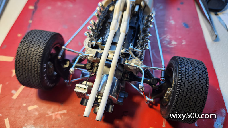
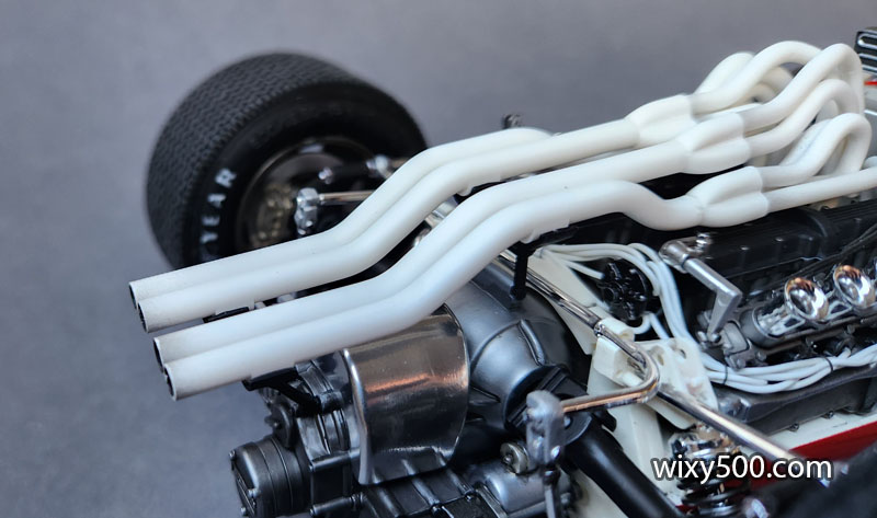
All exhaust pieces were primed with Tamiya White Primer, then Flat White (LP-4). Afterwards, the 12 header pipes received some Smoke colour on the end that was to be buried down in the ‘V’ of the engine block, and a light dusting of Flat Black on the end that gets inserted into the collector. Similarly, the exit hole of the main pipes were painted semi-gloss black and given a light dusting of Flat Black to represent exhaust soot on the tip (see later pic).
I start by adding the collector to the tail pipes, then fitting the three individual headers into each collector and used blind faith it would all line up ok because the pipes don’t actually attach to the engine (quite unrealistic!) and are supported only by the two rear mounting cradles.
Once the pipes were all painted and assembled, I glued the two inner systems first. Dry fitting prior suggested it was better this way than to start with the outer pipes.
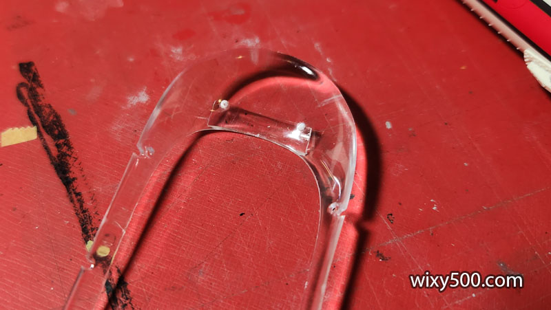
The clear windscreen has a small deflector on the front. I used Kristal Klear to fit this in place as it ends up drying clear.
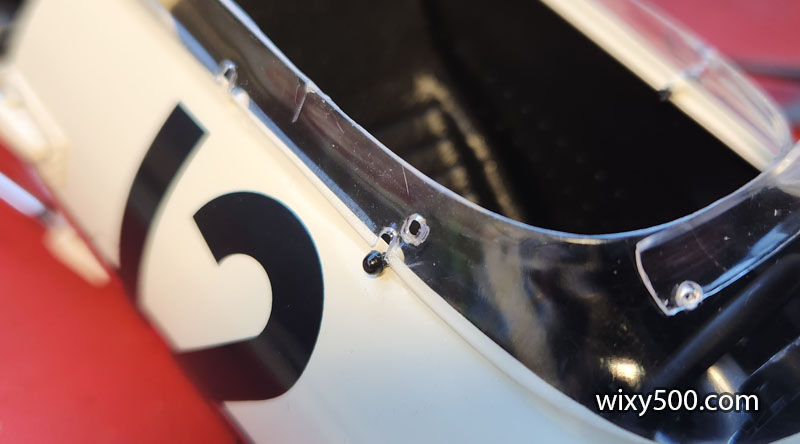
Six small studs hold the windscreen in place (yes, I know there are only 4 in the photo). Note the tailpipes at the top of pic with subtle soot dusting on the exits.
Unfortunately, the windscreen had a slight warp and combined with the out-of-square chassis, did not fit properly with very few of the mounting holes lining up properly. It was a case of fitting & gluing one pin, holding & waiting for it to cure, then working around the cockpit to the next one until eventually all six were done. In the end, it settled down not too bad, but the whole structure is under tension – who knows when it’s gonna go ‘twang’ and pop out of shape!
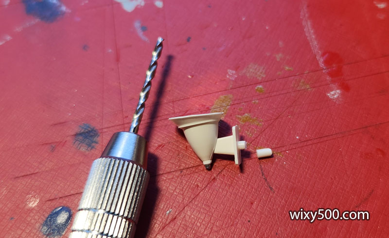
Mounting pins for the rear-view mirrors are excessively long, so I cut them shorter. The drill was needed to open the hole in the windscreen a little for the pin to actually fit. They were then glued on with Kristal Klear.
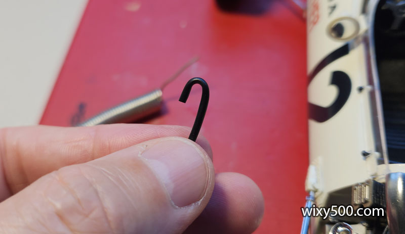
I decided to add some tubing (not part of the kit) to a tank, but the tube would not hold its shape when bent, so a small piece of solder was inserted, then bent.
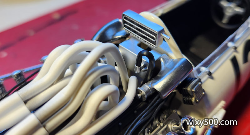
And fitted to the model. No idea where this went on the real car, but I think it’s better than having an exposed fitting that does nothing – like those on the oil cooler on the back of the rollover bar… Also, note the discolouration of the exhaust headers.
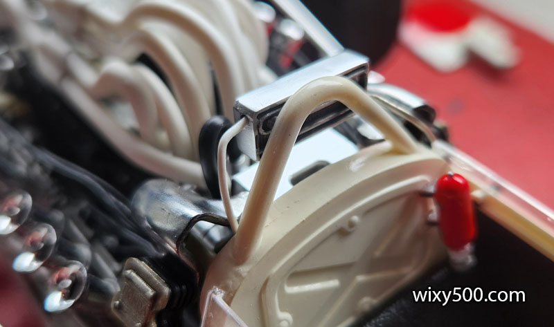
Above & Below: plumbing added to the oil cooler, made from scrap wire and solder. I cut the kit fittings off the cooler, then drilled small holes for the wire to fit into.
Exhaust pipe and rear end detail.
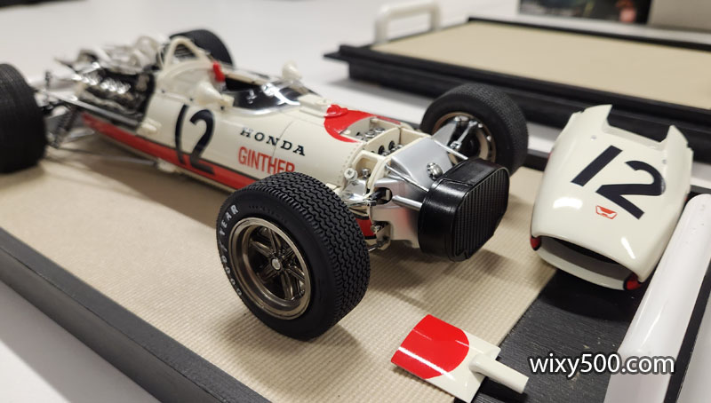
Nose cone and top panel are both removable.
Due to the consequence of the out-of-square chassis, the top panel and nose are not perfectly aligned when fitted.
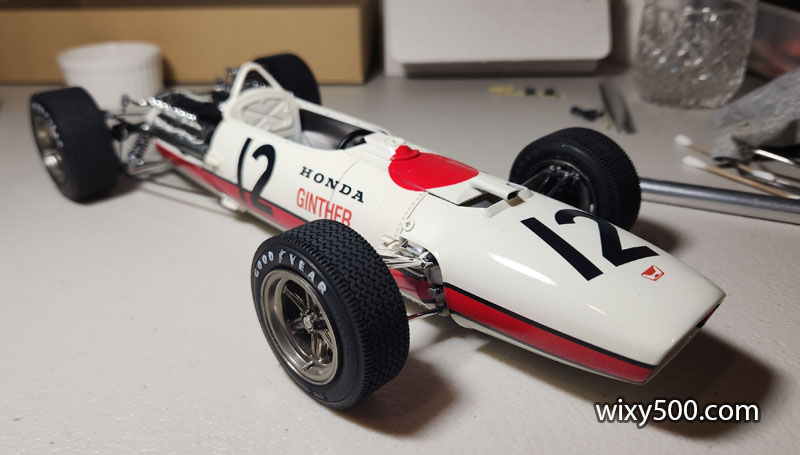
But overall, it looks like the 1966 Formula One Honda!
Conclusion
Despite the frustrations during the build and the sense of “I just want to get this over with”, it’s always satisfying to finish a model and then in retrospect it all doesn’t seem as bad!
Follow the instructions and this kit builds up into a decent representation of the Honda F1 car. For those who want to do a super-detail job, there’s plenty of scope for improvement as there are quite a few engine related pieces missing. However, to make it fully accurate, there’s a LOT of work to do.
Amazingly for its age, the tyres were not perished, though the decals were toast. In the end, painting the red on the body was probably the better way to go anyway.
If I could go back in time, I’d pay more attention to the initial chassis construction to make sure it was square. If I was to build another example, I’d maybe add some scratch-built parts for the throttle linkage and work out the true plumbing for the oil coolers, pump etc.
I have eight other unbuilt Tamiya 1:12 scale kits in the stash. Which one will I pull for the next build?
Obligatory closing shot – my build with the box art (11 Feb 2024).